
Why did you cut your intake down? Is it to high so the bonnet wont close? In that case, how much did you take off to get it to fit?
Cheers!
Howdy, Names Stirling
-
stirlsilver
- Posts: 339
- Joined: Tue Nov 21, 2006 9:45 am
- Location: Wheelers Hill, Victoria, Australia
- Contact:
The intake manifold is standard off another engine, I didn't cut anything. It fits perfectly well under the bonnet.
Stirling
Stirling
Stirling

Videos:
http://www.youtube.com/watch?v=a8Xljp6DD9g 17 June
http://www.youtube.com/watch?v=_mlJblv9iUo 24 May
& Others!
Videos:
http://www.youtube.com/watch?v=a8Xljp6DD9g 17 June
http://www.youtube.com/watch?v=_mlJblv9iUo 24 May
& Others!
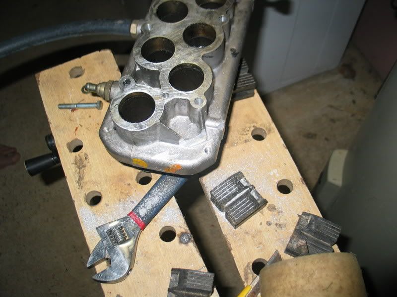
On http://i8.photobucket.com/albums/a16/st ... G_6661.jpg it looks like it has been chopped off a cm of so, at least I thought so.
Was nearly in panic that my measurements were wrong, luckily it isn't.
I see you also don't use the extra air valve that is normally fitted beside the thermostate housing. Any idea what that thing normaly does?
I thought it was for letting in the air when running idle because the throttle valve is completely closed? Or can I leave it away also?
Anyway, I am curious what the difference will be between your past setup and this!
-
stirlsilver
- Posts: 339
- Joined: Tue Nov 21, 2006 9:45 am
- Location: Wheelers Hill, Victoria, Australia
- Contact:
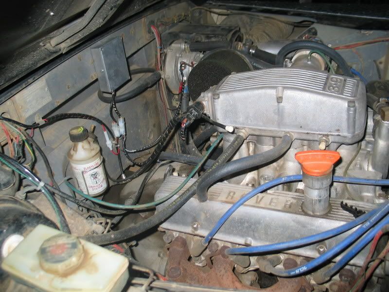
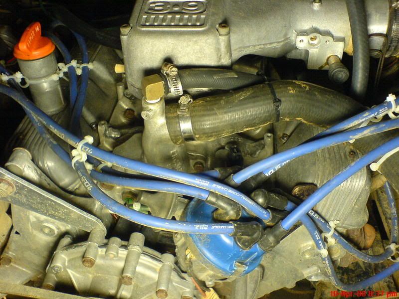
Ah, in that photo the filings are from the corner where we flattened it out and used the threaded hole to hold the throttle cable in place.
That black connector near the thermostat housing is actually another temperature sender that is used by the EFI system, while the other one is what goes to the gauge. The air valve is actually on the back of the plenum chamber and is driven by a stepper motor, I haven't determined if I want to use it yet. I've just blocked it off for the moment.
I set up the crank case breathers to circulate air through the engine from one tappet cover to the other and I'm pretty sure it is idling on that flow It still needs more tweaking tho.
The difference: Heaps more bottom end torque! and also it seems to rev out to a higher range, but that aluminium elbow I have used isn't ideal as it has steps in it and it is smaller then it should be. Will need to see what happens when I do the snorkel for it.
Stirling
That black connector near the thermostat housing is actually another temperature sender that is used by the EFI system, while the other one is what goes to the gauge. The air valve is actually on the back of the plenum chamber and is driven by a stepper motor, I haven't determined if I want to use it yet. I've just blocked it off for the moment.
I set up the crank case breathers to circulate air through the engine from one tappet cover to the other and I'm pretty sure it is idling on that flow
The difference: Heaps more bottom end torque! and also it seems to rev out to a higher range, but that aluminium elbow I have used isn't ideal as it has steps in it and it is smaller then it should be. Will need to see what happens when I do the snorkel for it.
Stirling
Stirling
Videos:
http://www.youtube.com/watch?v=a8Xljp6DD9g 17 June
http://www.youtube.com/watch?v=_mlJblv9iUo 24 May
& Others!
Videos:
http://www.youtube.com/watch?v=a8Xljp6DD9g 17 June
http://www.youtube.com/watch?v=_mlJblv9iUo 24 May
& Others!
Now it becomes clear why you attatched one hose from the rockercover to the connection in front of the throttle valve! I aready askes myself why you did that but now I see!
If it works properly, please share it. Then I can dump that valve also
The other sensor in the inlet besides the theromstate housing is just an on/off switch for the electronic fan. I have my sensor in the inlet hose to the radiator so I'll blank that one off.
I'm sooo eager to have my first testrun on my car, but it stil needs quite a lot of work..
-
stirlsilver
- Posts: 339
- Joined: Tue Nov 21, 2006 9:45 am
- Location: Wheelers Hill, Victoria, Australia
- Contact:
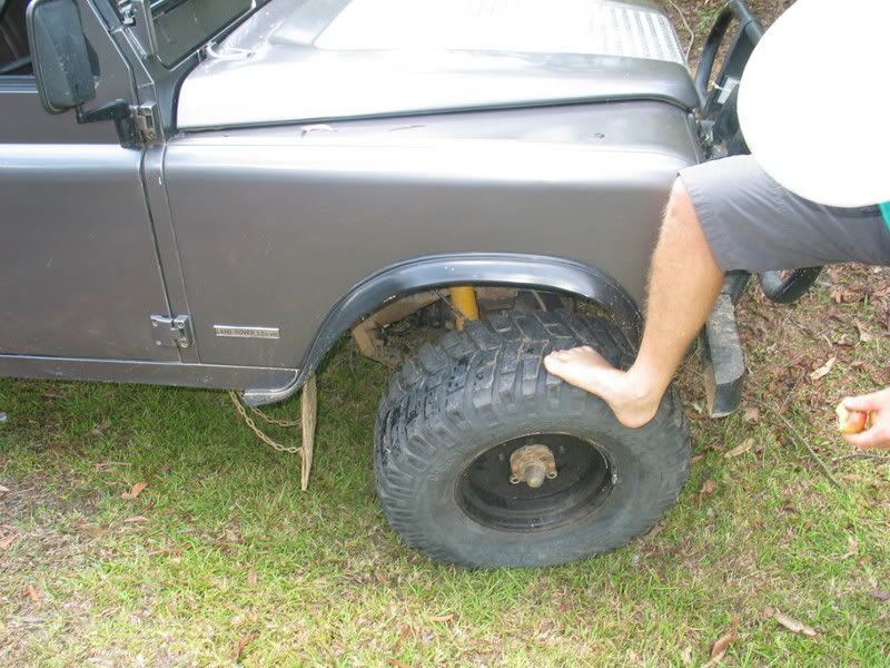
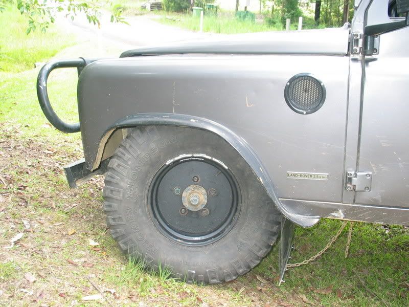
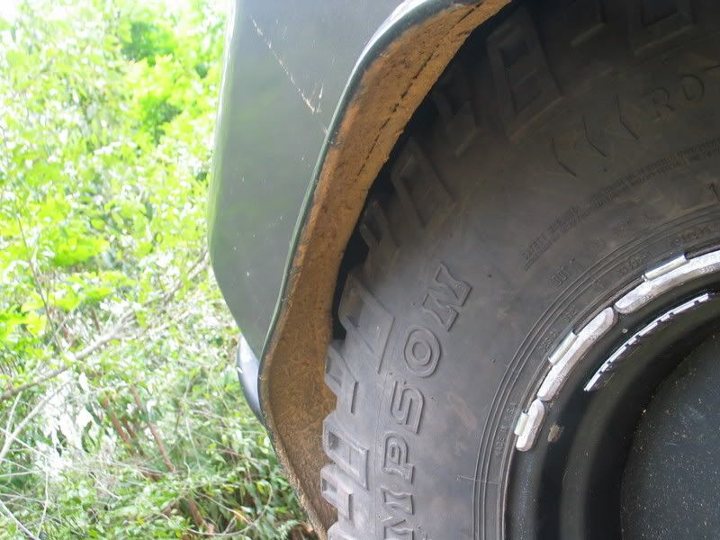
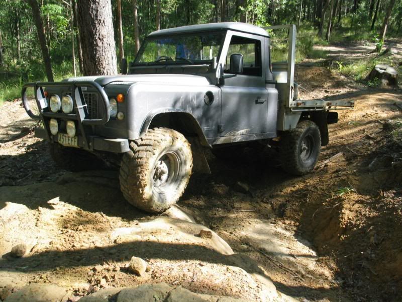
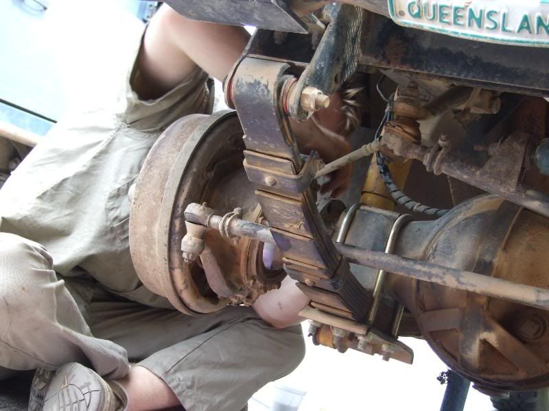
OK! I did a trial fit of the 33"x12.5" claws today and thankfully I don't need to cut the guards! Altho I probably should limit my steering slightly. Here are the photos. I'll check the rear when I get hold of a full set of wheel nuts.
Stirling
Stirling
Stirling
Videos:
http://www.youtube.com/watch?v=a8Xljp6DD9g 17 June
http://www.youtube.com/watch?v=_mlJblv9iUo 24 May
& Others!
Videos:
http://www.youtube.com/watch?v=a8Xljp6DD9g 17 June
http://www.youtube.com/watch?v=_mlJblv9iUo 24 May
& Others!
-
stirlsilver
- Posts: 339
- Joined: Tue Nov 21, 2006 9:45 am
- Location: Wheelers Hill, Victoria, Australia
- Contact:
Hey all,
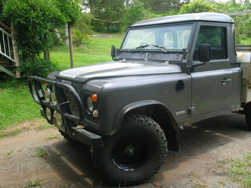
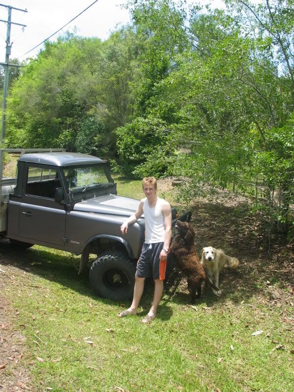
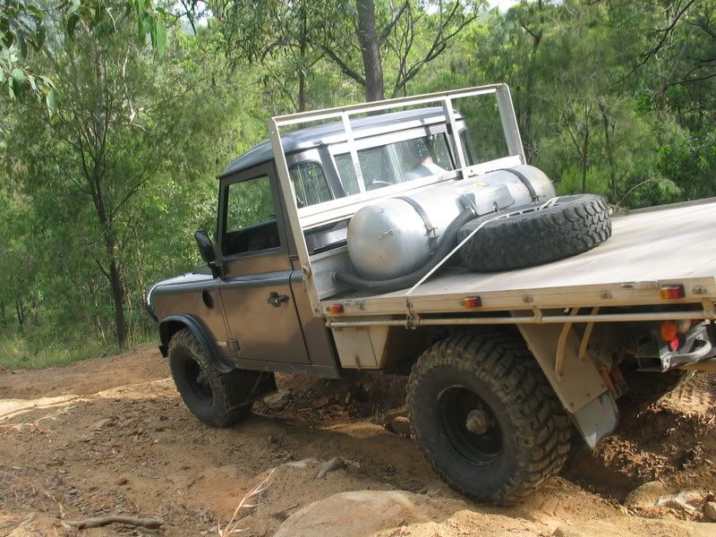
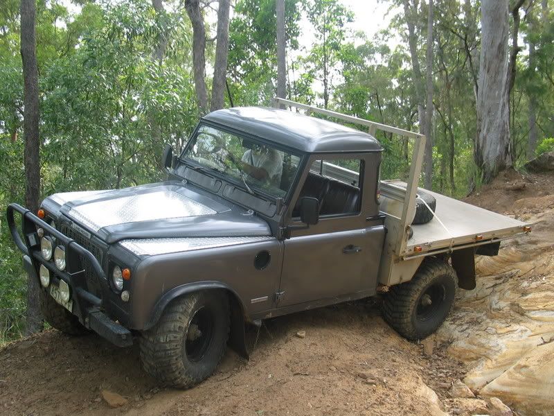
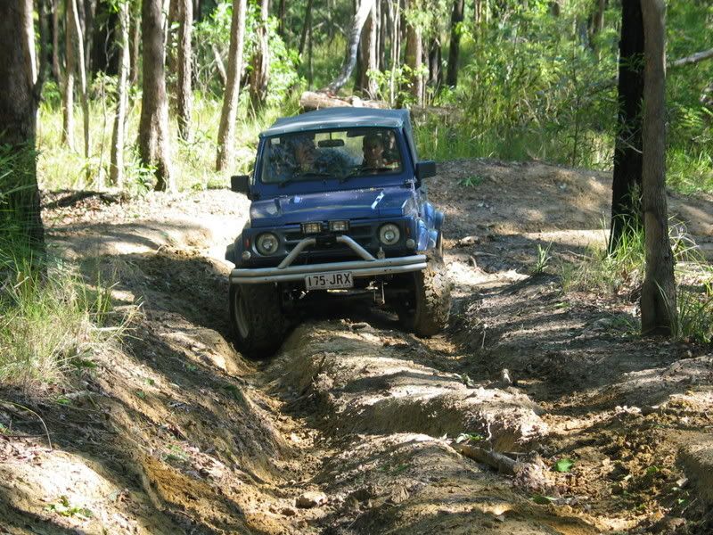
Yesterday myself and my friend headed out into the glasshouse mountains forestry tracks to try out our new tyres. I've gone from 30"x9.5" to 33"x12.5" and my friend went from 33"x12.5" to 35"x10.5". Here are some of the photos. Also I fitted the checker plate on the wings of the car!
And a video:
http://www.youtube.com/watch?v=WCFxpqqigyc
Stirling
Videos:
http://www.youtube.com/watch?v=a8Xljp6DD9g 17 June
http://www.youtube.com/watch?v=_mlJblv9iUo 24 May
& Others!
Videos:
http://www.youtube.com/watch?v=a8Xljp6DD9g 17 June
http://www.youtube.com/watch?v=_mlJblv9iUo 24 May
& Others!
-
stirlsilver
- Posts: 339
- Joined: Tue Nov 21, 2006 9:45 am
- Location: Wheelers Hill, Victoria, Australia
- Contact:
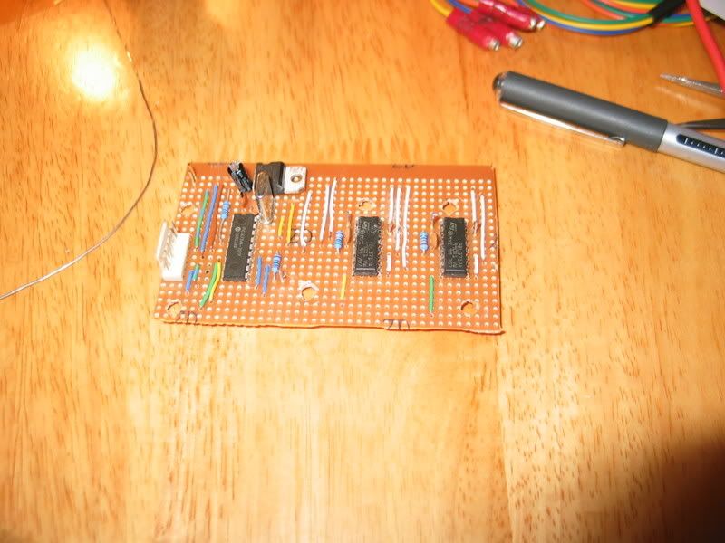
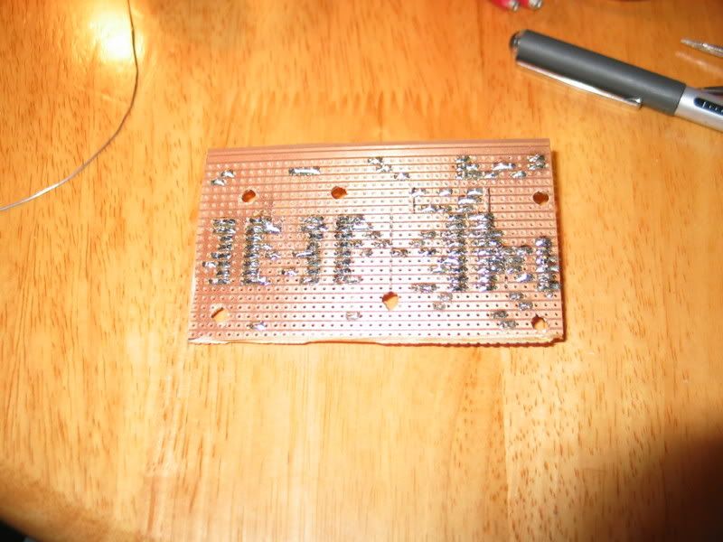
Ok, I've started making some progress on that idle valve... Being a stepper motor I had to use some stepper motor IC's that could be driven by a programmable micro controller. I've built up the circuit on some veroboard and programmed the micro controller and it seems to work!!
The way this works is that I have mounted a thermo switch on my LPG evaporator (when it is cold the engine doesn't like to idle). The micro controller checks to see if the evaporator is cold. If it is, it opens the idle valve by a set amount until the evaporator warms up and trips the thermo switch in which case the micro controller then closes the idle valve.
Will test it out on the engine tomorrow.
Here is some photos of what has been involved so far:
Stirling
Videos:
http://www.youtube.com/watch?v=a8Xljp6DD9g 17 June
http://www.youtube.com/watch?v=_mlJblv9iUo 24 May
& Others!
Videos:
http://www.youtube.com/watch?v=a8Xljp6DD9g 17 June
http://www.youtube.com/watch?v=_mlJblv9iUo 24 May
& Others!
-
stirlsilver
- Posts: 339
- Joined: Tue Nov 21, 2006 9:45 am
- Location: Wheelers Hill, Victoria, Australia
- Contact:
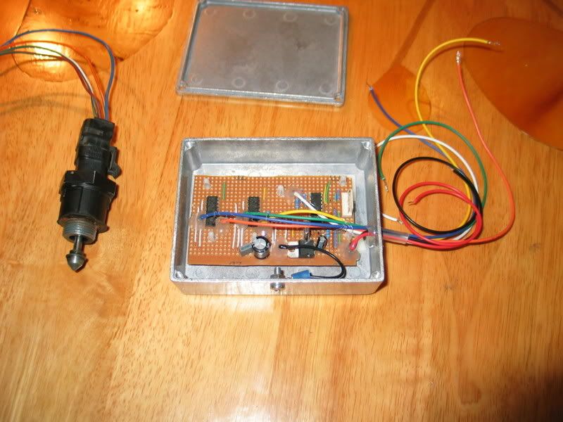
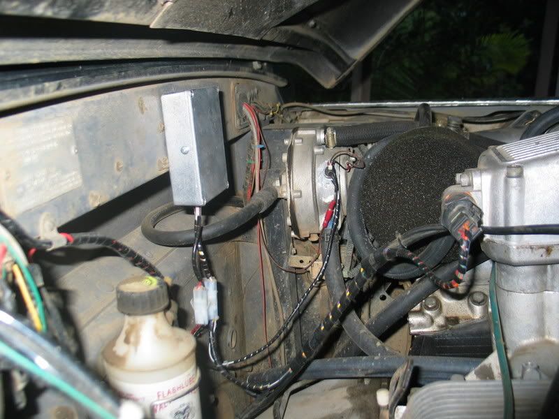
Ok, well I installed the idle valve controller and it works!!! I can now start the engine and take my foot of the pedal when it is cold and it will idle! Hurrah!!
I'm quite proud of how it all turned out, considering I designed the whole thing and it is my first application of a microcontroller
Here are a couple of photos of the unit installed:
Stirling
I'm quite proud of how it all turned out, considering I designed the whole thing and it is my first application of a microcontroller
Here are a couple of photos of the unit installed:
Stirling
Stirling
Videos:
http://www.youtube.com/watch?v=a8Xljp6DD9g 17 June
http://www.youtube.com/watch?v=_mlJblv9iUo 24 May
& Others!
Videos:
http://www.youtube.com/watch?v=a8Xljp6DD9g 17 June
http://www.youtube.com/watch?v=_mlJblv9iUo 24 May
& Others!
-
stirlsilver
- Posts: 339
- Joined: Tue Nov 21, 2006 9:45 am
- Location: Wheelers Hill, Victoria, Australia
- Contact:
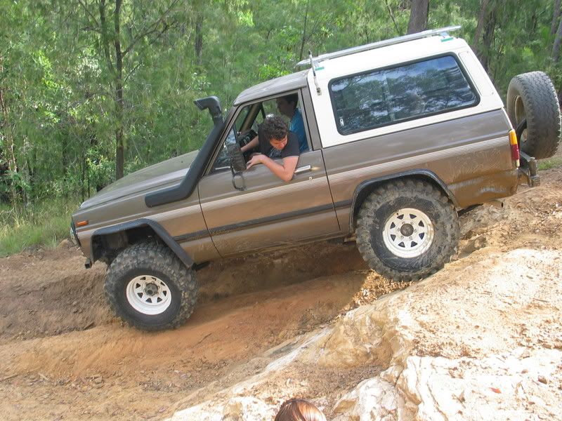
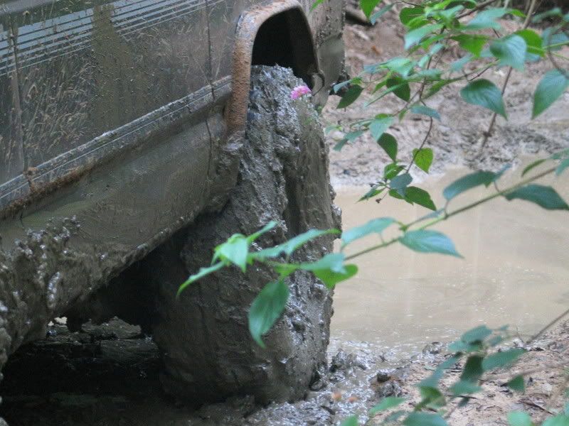
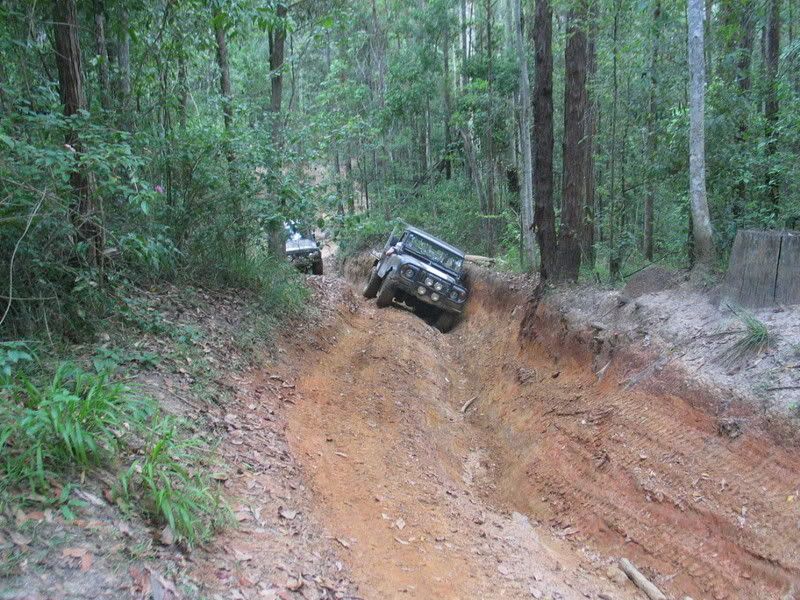
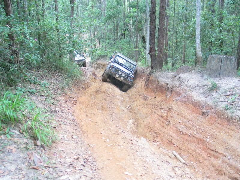
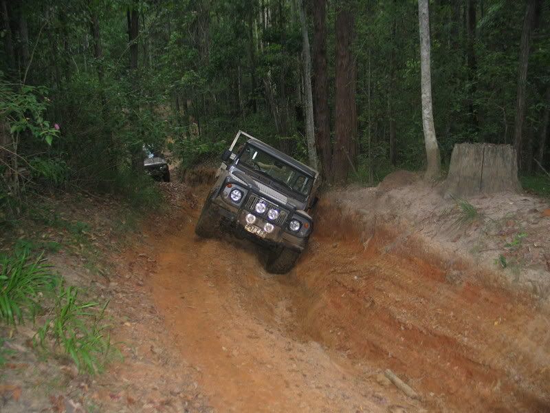
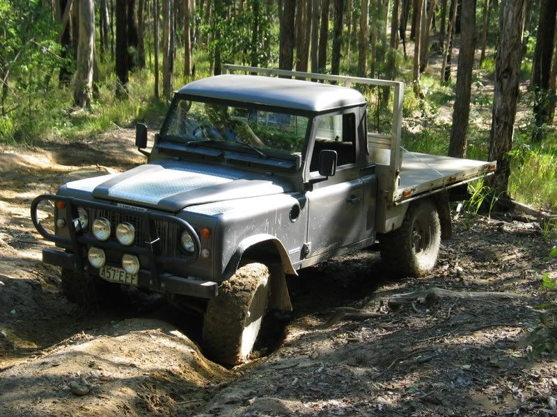
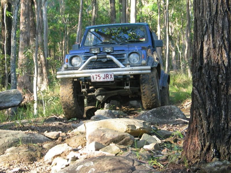
I thought I would also post up some photos of myself and a few friends heading up the radio tower track off old caloundra rd. All the rain certainly did make things... interesting. Take a look at the photos!
Me negotiating some of the easier stuff:
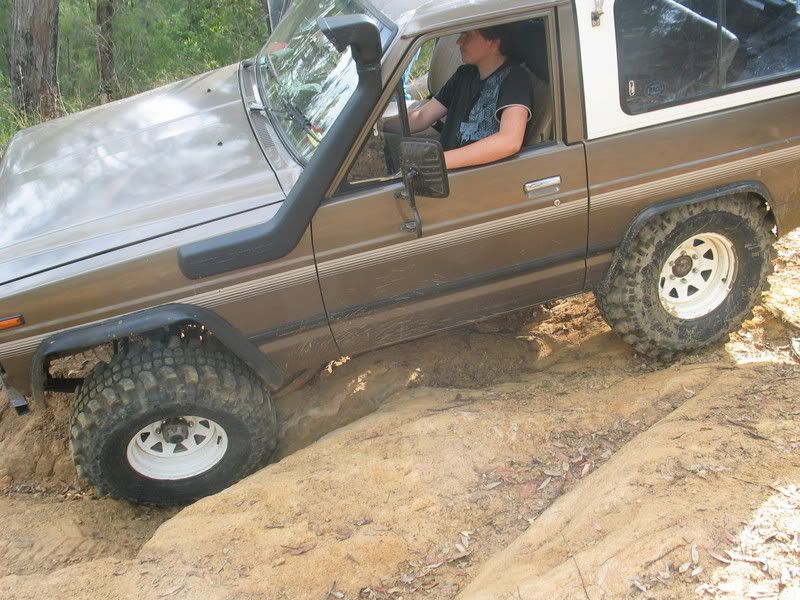
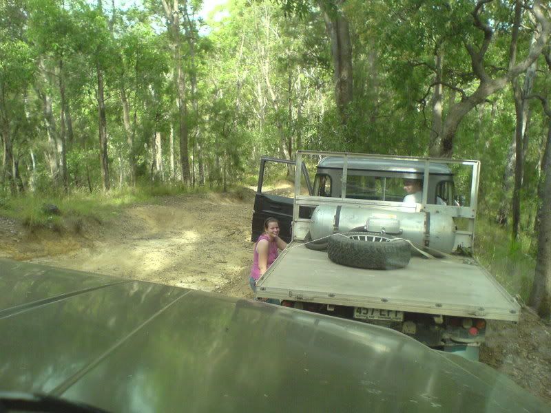
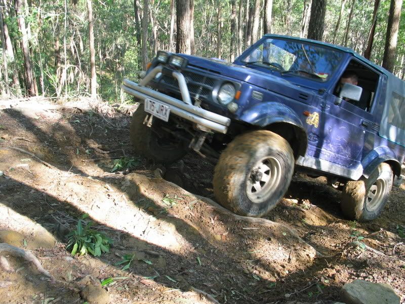
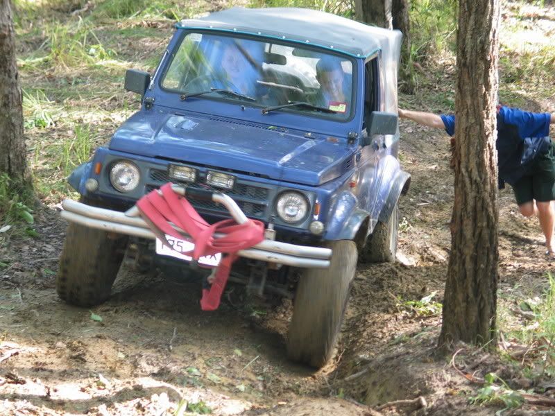
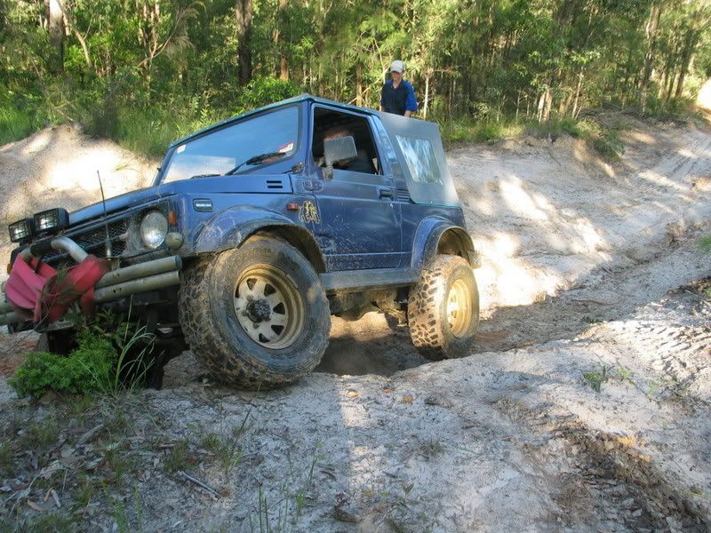
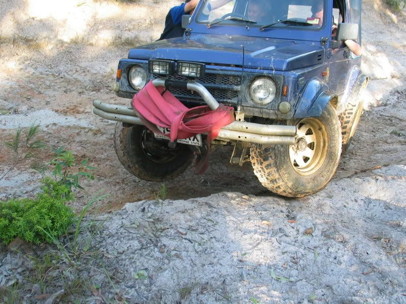
The suzy, it was experiencing some carby problems on the slopes which made things so much harder up the hill:
Hmm... nothing exciting in these:
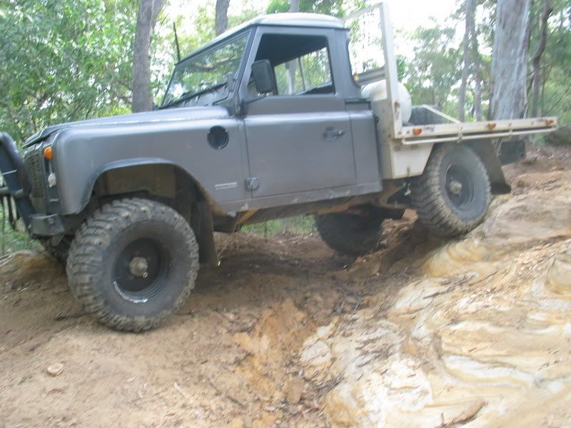
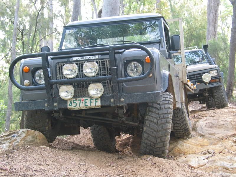
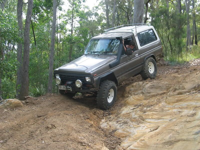
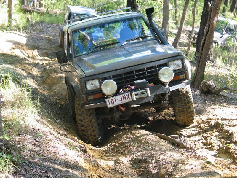
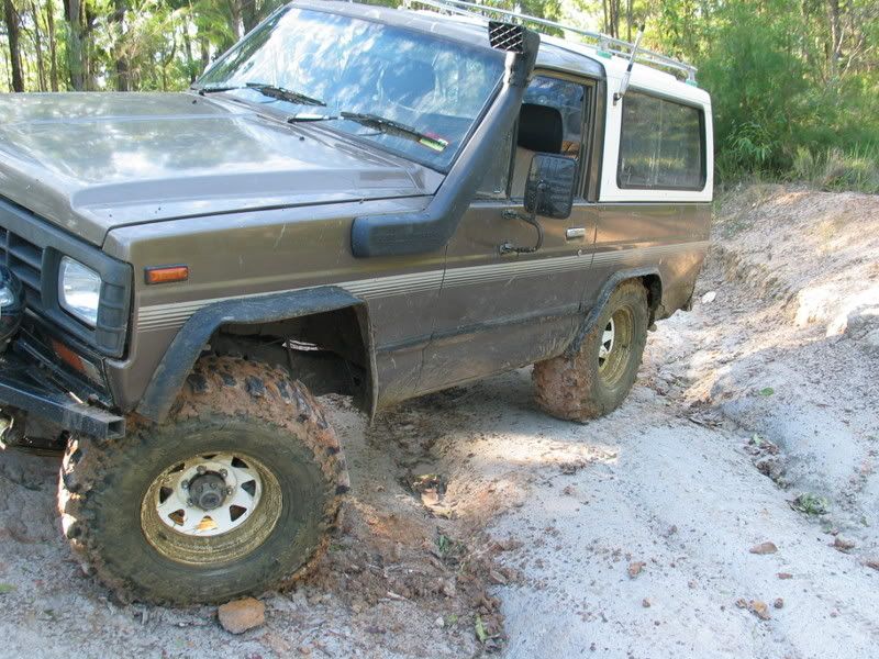
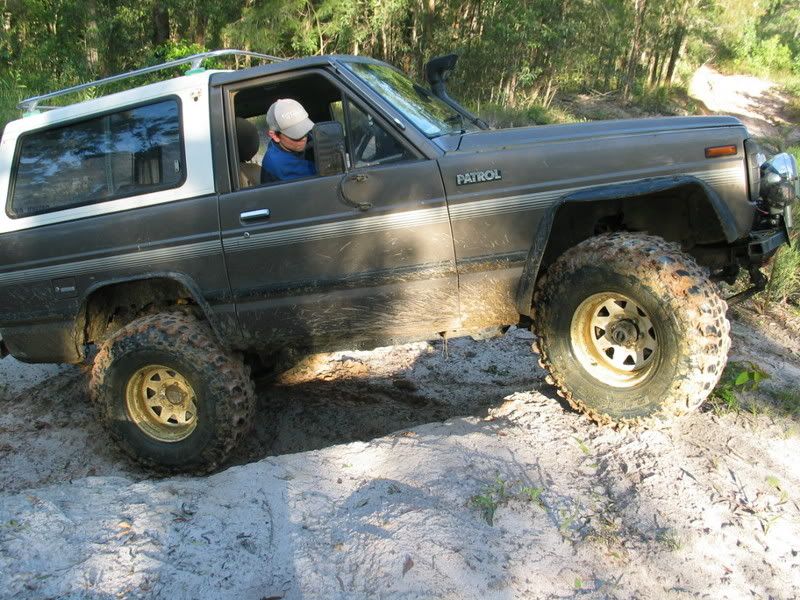
The twin locked patrol:
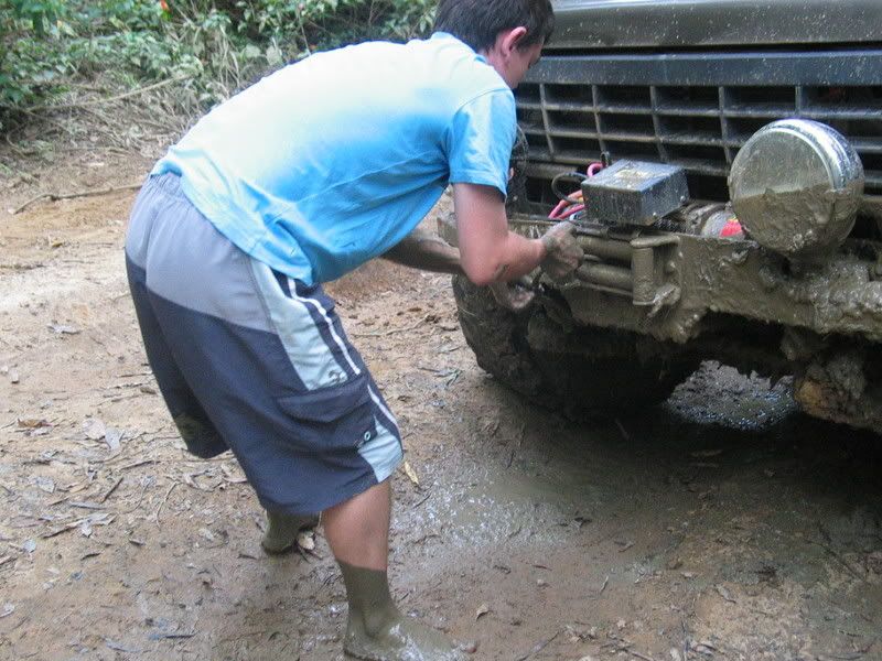
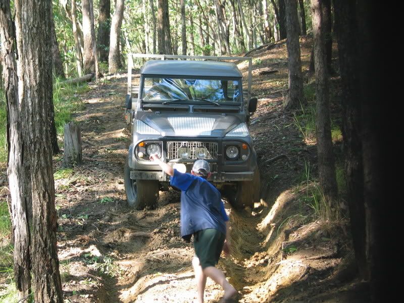
Here is the suzy again, we actually resorted to helping it up the hill by pushing it!!:
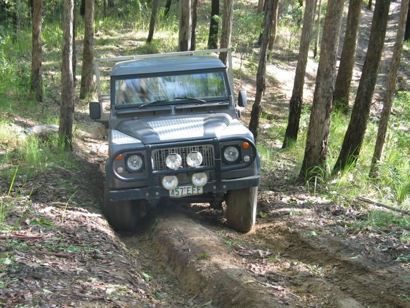
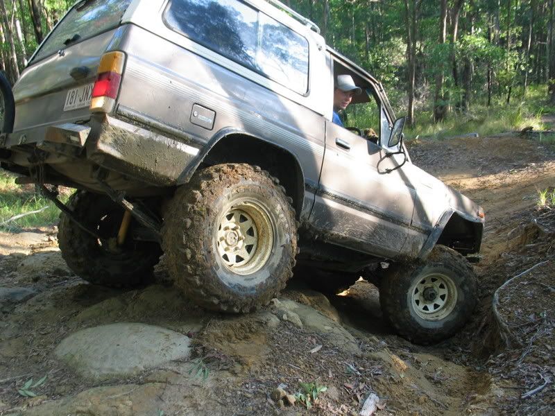
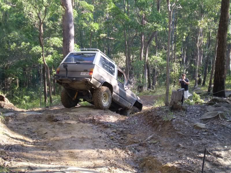
Me getting up the steep part without resorting to using the front locker, needed plenty of right foot!:
We found a nice embankment and took the opportunity to see how the cars articulated:
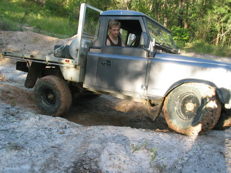
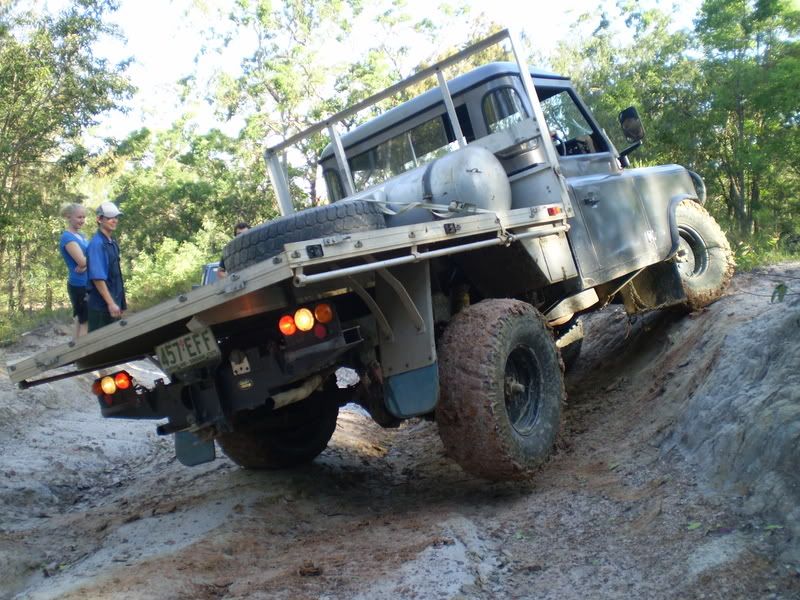
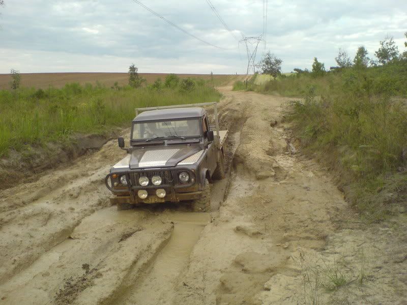
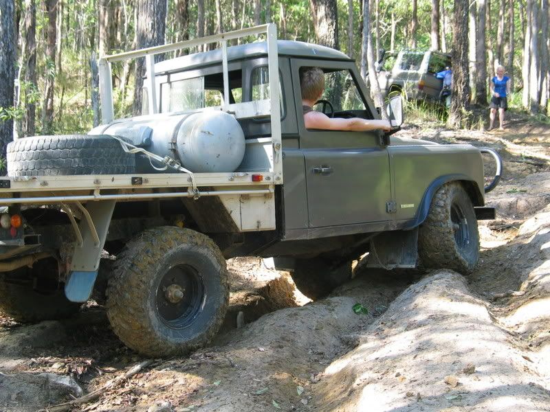
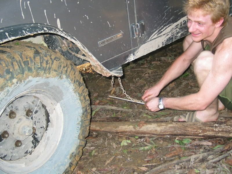
On the way back down, the ruts kept pushing me too close to the tree and I could not go through without bending the frame above my tray:
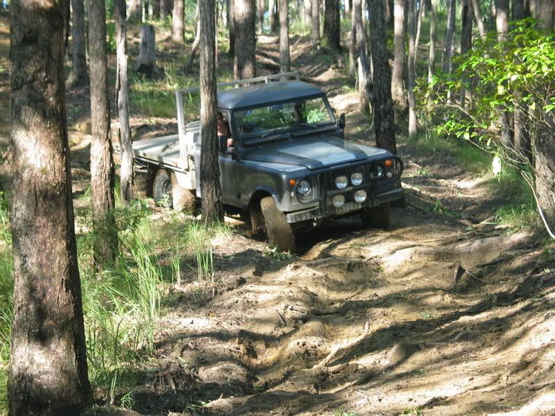
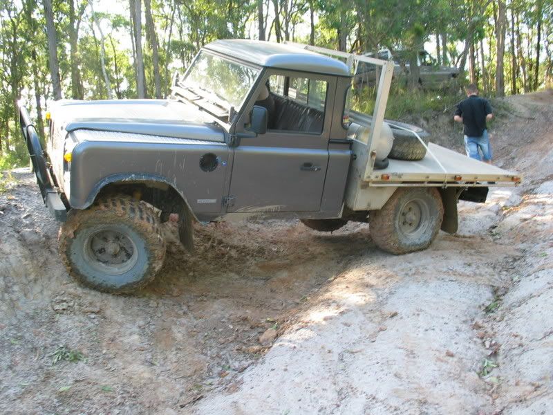
Had to reverse up the steep muddy track:
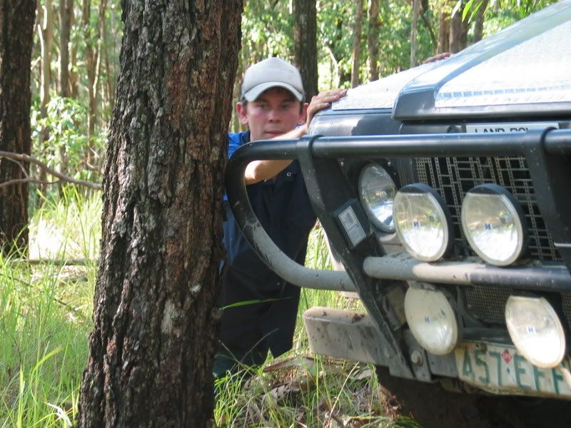
Slipped into another set of ruts further up and slid in between two trees:
Eventually got out, only damage was my newly replaced mud flap got torn off again when reversing!!:
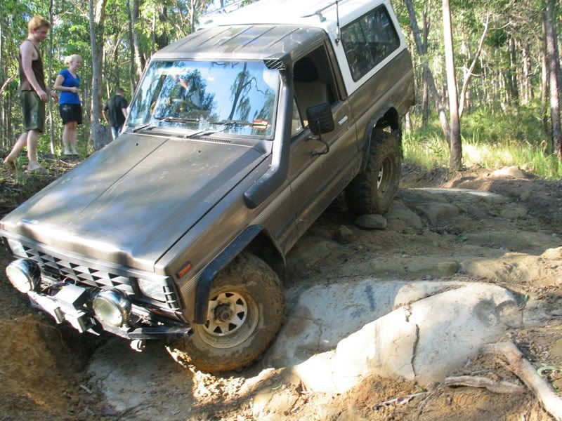
My friend in the patrol got cocky and tried a much harder way down and got stuck in a nasty position:

Another Shot of the suzy:
Me negotiating some of the easier stuff:
The suzy, it was experiencing some carby problems on the slopes which made things so much harder up the hill:
Hmm... nothing exciting in these:
The twin locked patrol:
Here is the suzy again, we actually resorted to helping it up the hill by pushing it!!:
Me getting up the steep part without resorting to using the front locker, needed plenty of right foot!:
We found a nice embankment and took the opportunity to see how the cars articulated:
On the way back down, the ruts kept pushing me too close to the tree and I could not go through without bending the frame above my tray:
Had to reverse up the steep muddy track:
Slipped into another set of ruts further up and slid in between two trees:
Eventually got out, only damage was my newly replaced mud flap got torn off again when reversing!!:
My friend in the patrol got cocky and tried a much harder way down and got stuck in a nasty position:
Another Shot of the suzy:
Stirling
Videos:
http://www.youtube.com/watch?v=a8Xljp6DD9g 17 June
http://www.youtube.com/watch?v=_mlJblv9iUo 24 May
& Others!
Videos:
http://www.youtube.com/watch?v=a8Xljp6DD9g 17 June
http://www.youtube.com/watch?v=_mlJblv9iUo 24 May
& Others!
-
stirlsilver
- Posts: 339
- Joined: Tue Nov 21, 2006 9:45 am
- Location: Wheelers Hill, Victoria, Australia
- Contact:
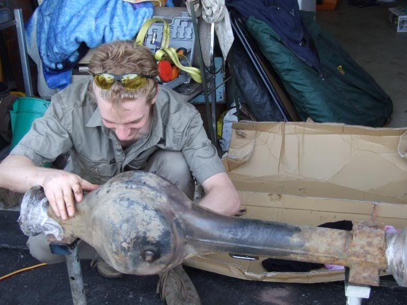
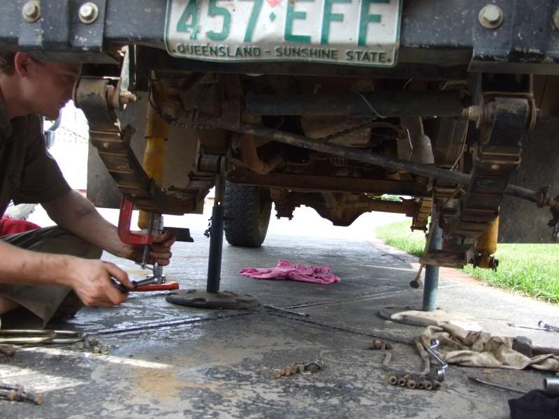
Hi all, at long last the vibration problems that I have been experiencing ever since I fitted the maxi drive to my series 3 stage 1, are sorted! The whole problem was as a result of using a series 2 diff housing on the car resulting in incorrect drive line geometry.
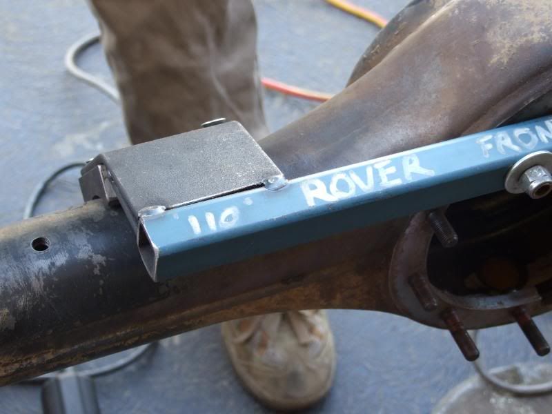
The Solution... putting the old diff housing back into the car! Anyway to do this required fitting an actuator block onto the other housing. I wouldn't have been able to do this without the help of various people here! We took a few photos of everything we did for the sake of sharing it with you guys.
Here are the photos:
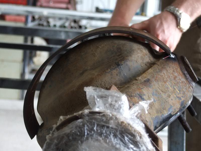
Preparing the diff housing to use the jig. All contact faces must be clean so the jig sits in the right place.
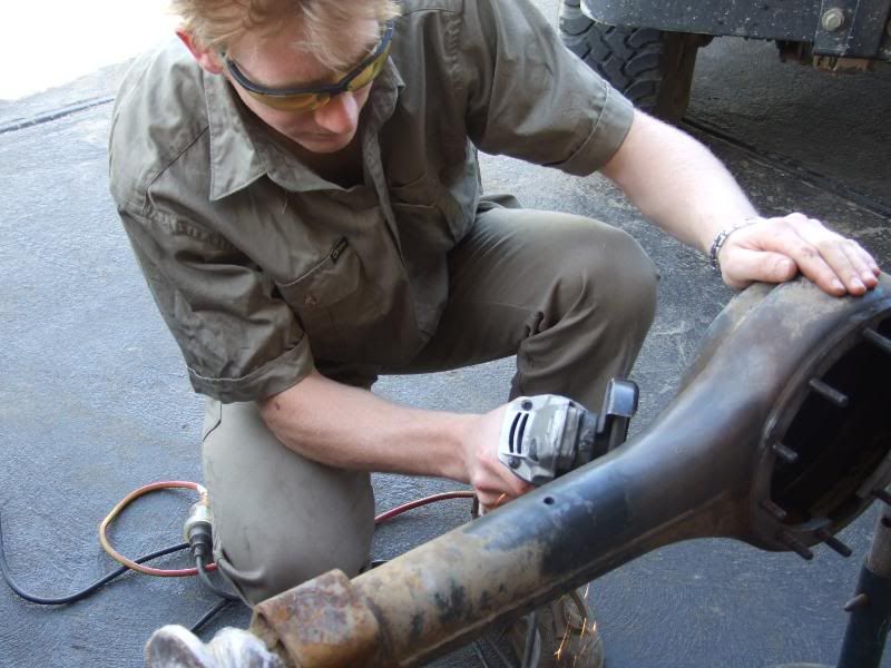
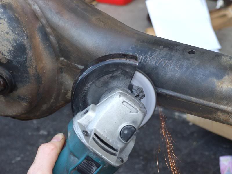
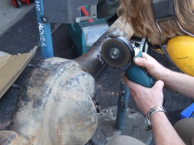
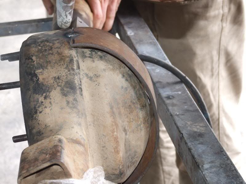
Grinding of the weld seam that was preventing the block from sitting in the right spot.
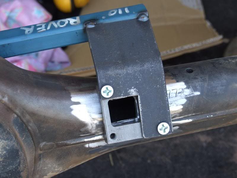
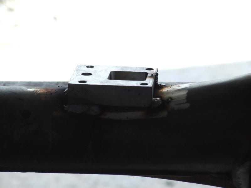
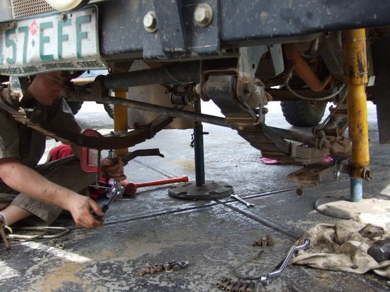
The jig and block sitting in the right position.
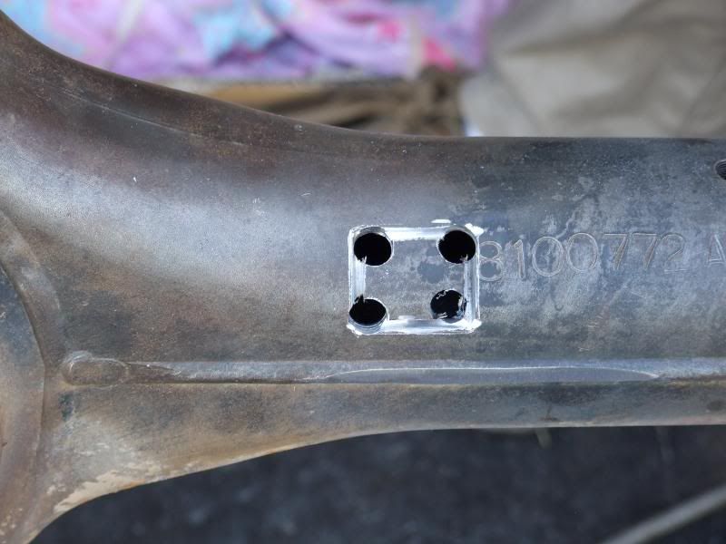
The scribed hole that is required to be cut. A sharpened screw driver works surprisingly well for this!
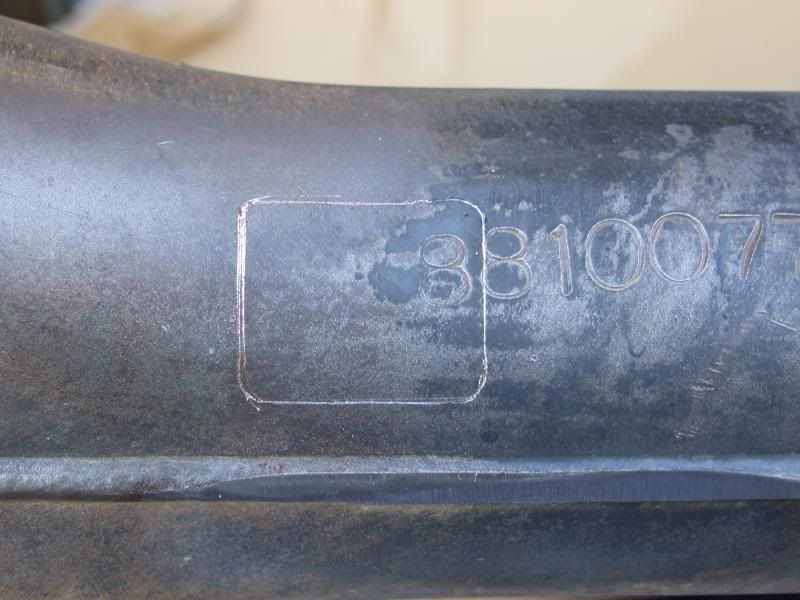
Just a quick lesson we learnt some time down the track... mark/cut the hole larger then necessary to ensure that the actuator arm will fit through!!!
Drill holes in the corners. And cut as deep as you can with an angle grinder.
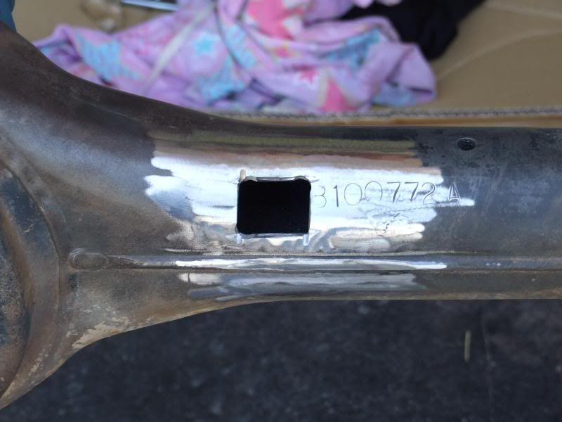
Once you have gone as deep as you can, use a jigsaw to cut the remaining material.
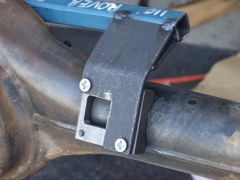
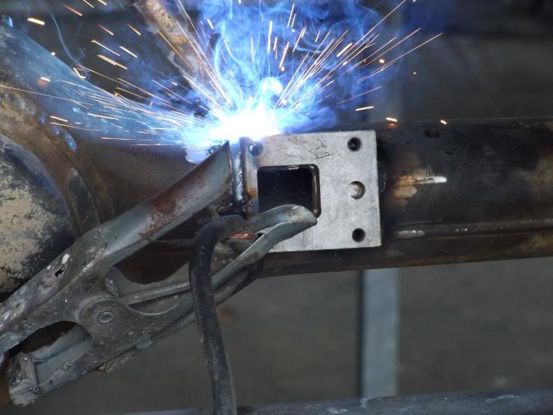
The hole.
And how it all sits together.
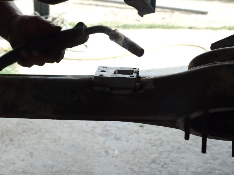
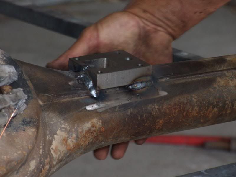
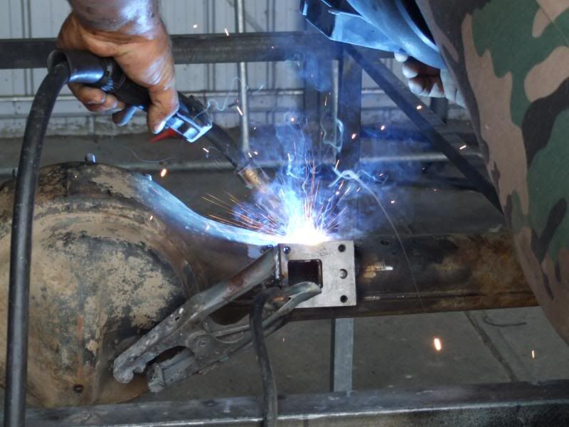
Welding, if you do it slowly enough and doing the corners evenly you can get away with not having to pre-stress the housing.
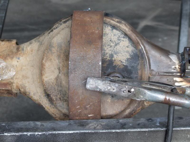
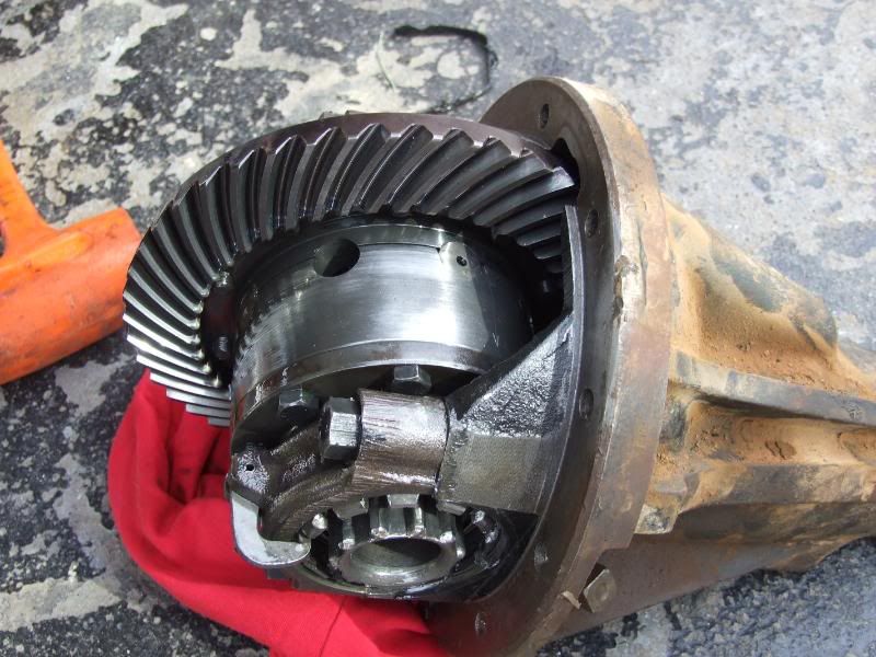
While we were waiting for it to cool, we fitted some crown wheel protection.
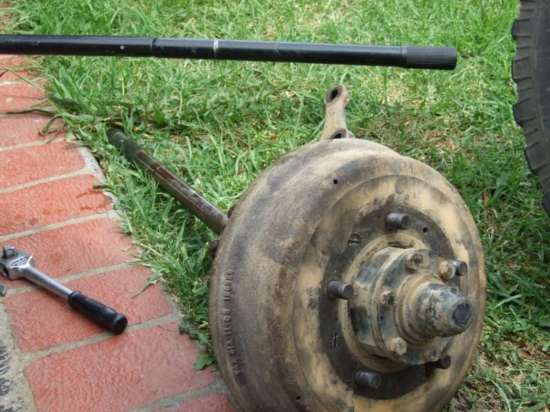
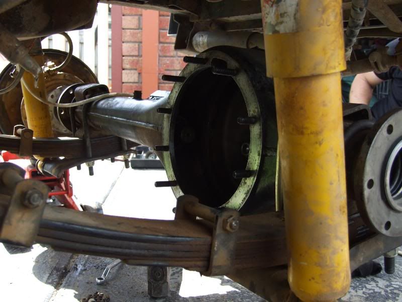
Removal of the old housing.
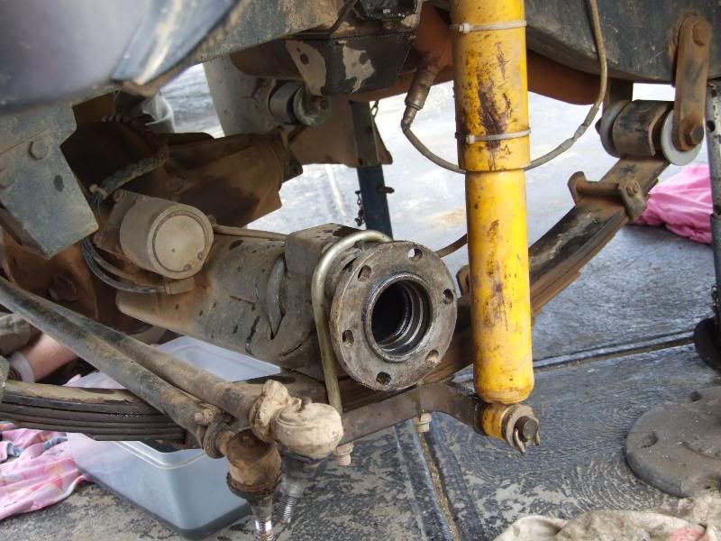
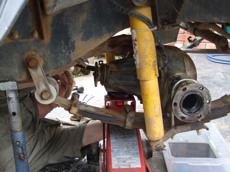
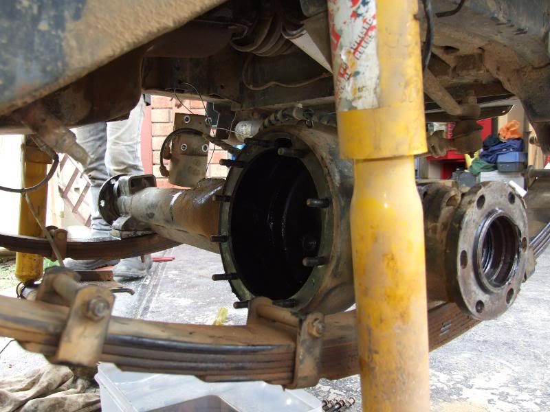
Fit the original housing back in.
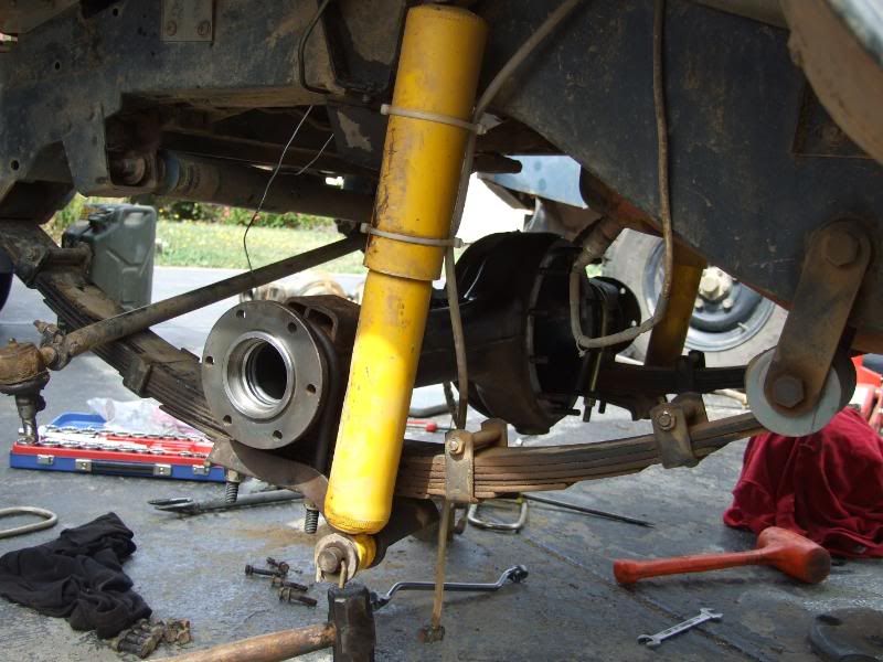
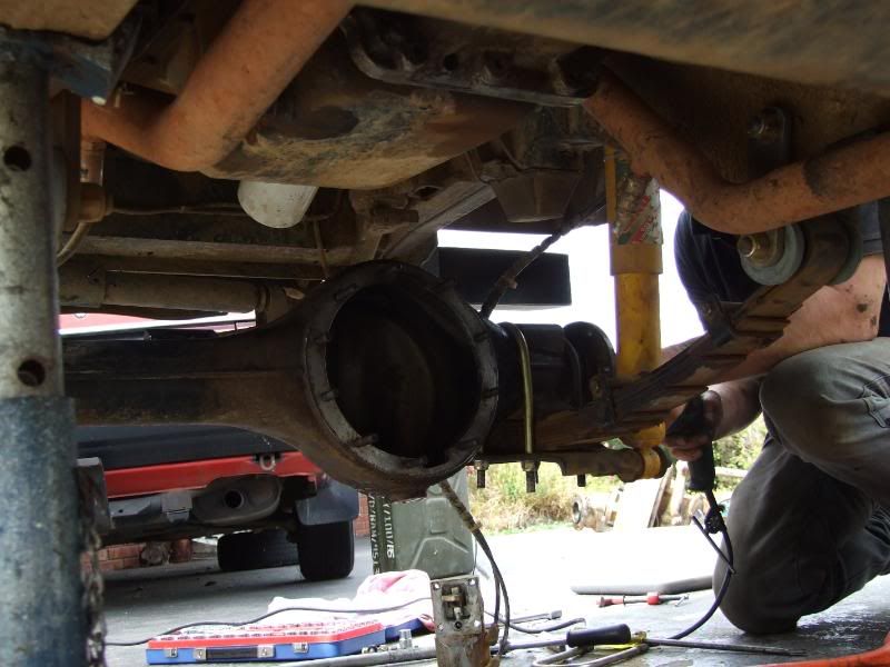
Just a shot of the diff... this is the diff I had to tinker with to make it fit... 2mm off the maxi drive flange and 2mm off the back of the crown wheel.
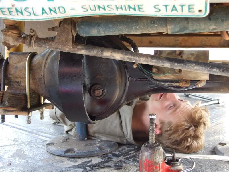
And start to bolt it all back together!
Took the most part of a day, but it solved the vibration problems... Problems that not even 10degree caster wedges couldn't fix!
The Solution... putting the old diff housing back into the car! Anyway to do this required fitting an actuator block onto the other housing. I wouldn't have been able to do this without the help of various people here! We took a few photos of everything we did for the sake of sharing it with you guys.
Here are the photos:
Preparing the diff housing to use the jig. All contact faces must be clean so the jig sits in the right place.
Grinding of the weld seam that was preventing the block from sitting in the right spot.
The jig and block sitting in the right position.
The scribed hole that is required to be cut. A sharpened screw driver works surprisingly well for this!
Just a quick lesson we learnt some time down the track... mark/cut the hole larger then necessary to ensure that the actuator arm will fit through!!!
Drill holes in the corners. And cut as deep as you can with an angle grinder.
Once you have gone as deep as you can, use a jigsaw to cut the remaining material.
The hole.
And how it all sits together.
Welding, if you do it slowly enough and doing the corners evenly you can get away with not having to pre-stress the housing.
While we were waiting for it to cool, we fitted some crown wheel protection.
Removal of the old housing.
Fit the original housing back in.
Just a shot of the diff... this is the diff I had to tinker with to make it fit... 2mm off the maxi drive flange and 2mm off the back of the crown wheel.
And start to bolt it all back together!
Took the most part of a day, but it solved the vibration problems... Problems that not even 10degree caster wedges couldn't fix!
Stirling
Videos:
http://www.youtube.com/watch?v=a8Xljp6DD9g 17 June
http://www.youtube.com/watch?v=_mlJblv9iUo 24 May
& Others!
Videos:
http://www.youtube.com/watch?v=a8Xljp6DD9g 17 June
http://www.youtube.com/watch?v=_mlJblv9iUo 24 May
& Others!
-
stirlsilver
- Posts: 339
- Joined: Tue Nov 21, 2006 9:45 am
- Location: Wheelers Hill, Victoria, Australia
- Contact:
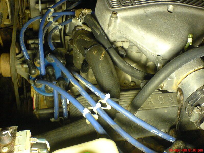
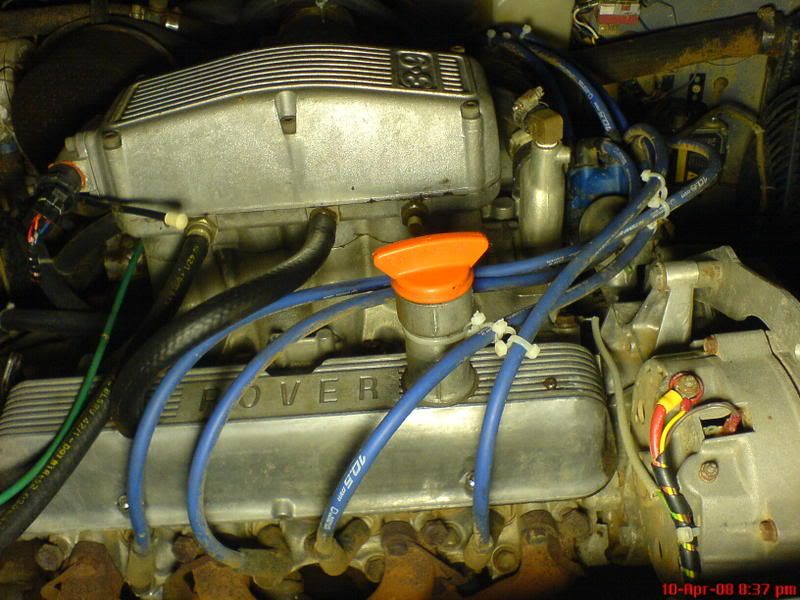
Right... well i've gotten sick of my ignition leads leaking on me so tonight I decided to do something about it.
I had already tried once before to sort the problem but when I checked tonight in the dark, you would throttle the car rapidly and you would get a light show under the bonnet!
Sigh... the problems of 12:1 CR... not even 10.5mm leads can handle it... anyway, here is what I resorted to... zip ties... Works surprisingly well! Reduced the problem substantially! But not completely eliminated...
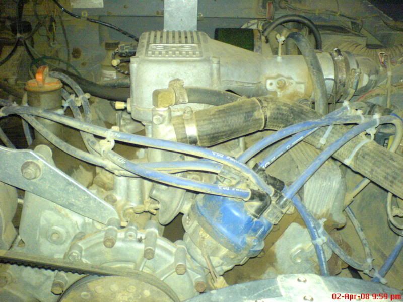
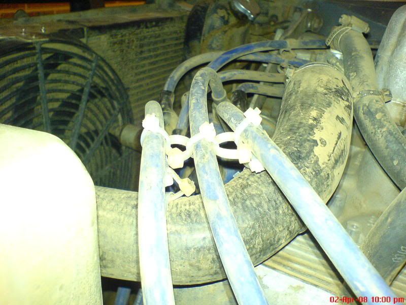
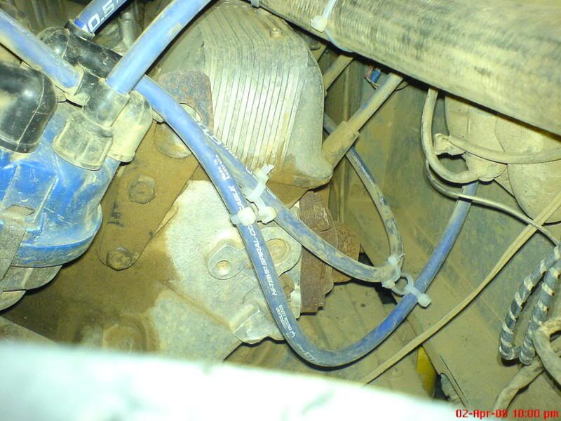
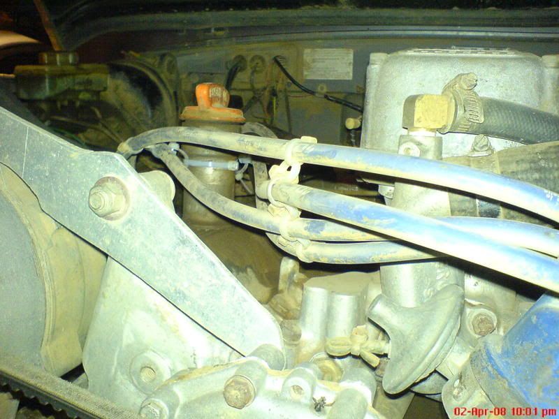
Probably better when the engine is washed eh??
I had already tried once before to sort the problem but when I checked tonight in the dark, you would throttle the car rapidly and you would get a light show under the bonnet!
Sigh... the problems of 12:1 CR... not even 10.5mm leads can handle it... anyway, here is what I resorted to... zip ties... Works surprisingly well! Reduced the problem substantially! But not completely eliminated...
Probably better when the engine is washed eh??
Stirling
Videos:
http://www.youtube.com/watch?v=a8Xljp6DD9g 17 June
http://www.youtube.com/watch?v=_mlJblv9iUo 24 May
& Others!
Videos:
http://www.youtube.com/watch?v=a8Xljp6DD9g 17 June
http://www.youtube.com/watch?v=_mlJblv9iUo 24 May
& Others!
-
stirlsilver
- Posts: 339
- Joined: Tue Nov 21, 2006 9:45 am
- Location: Wheelers Hill, Victoria, Australia
- Contact:
Ok! I'm starting to take the necessary steps to fit the LPG mixer ring I designed... I had forgotten that the throttle body on my engine isn't 3" so I had to do some further machining to the mixer ring.
Anyway here is where I am at so far:
The mixer ring as per the design
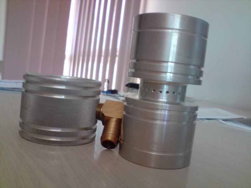
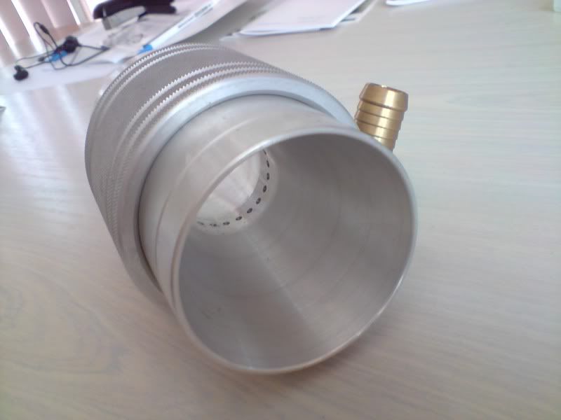
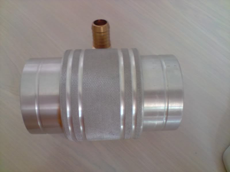
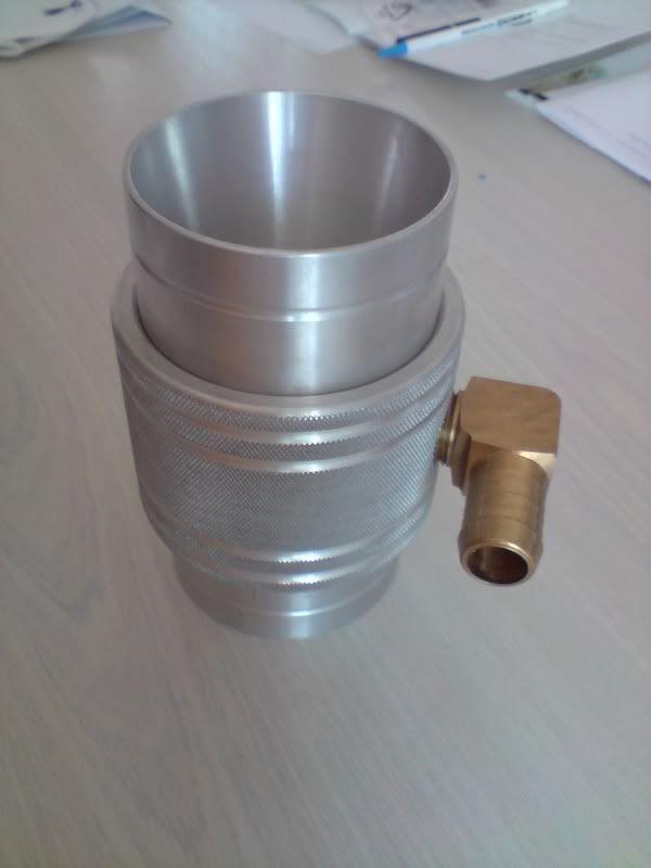
Now the mixer ring with the necessary machining to bring the ID to 65mm
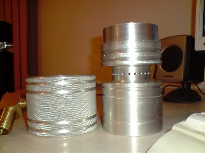
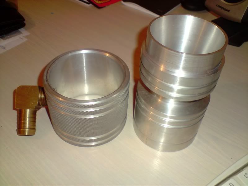
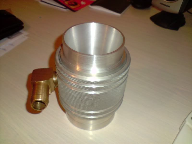
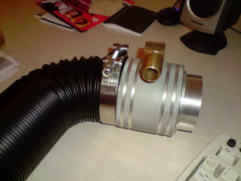
It should all be going under the bonnet very soon!!
Anyway here is where I am at so far:
The mixer ring as per the design
Now the mixer ring with the necessary machining to bring the ID to 65mm
It should all be going under the bonnet very soon!!
Stirling
Videos:
http://www.youtube.com/watch?v=a8Xljp6DD9g 17 June
http://www.youtube.com/watch?v=_mlJblv9iUo 24 May
& Others!
Videos:
http://www.youtube.com/watch?v=a8Xljp6DD9g 17 June
http://www.youtube.com/watch?v=_mlJblv9iUo 24 May
& Others!
-
stirlsilver
- Posts: 339
- Joined: Tue Nov 21, 2006 9:45 am
- Location: Wheelers Hill, Victoria, Australia
- Contact:
Ok,
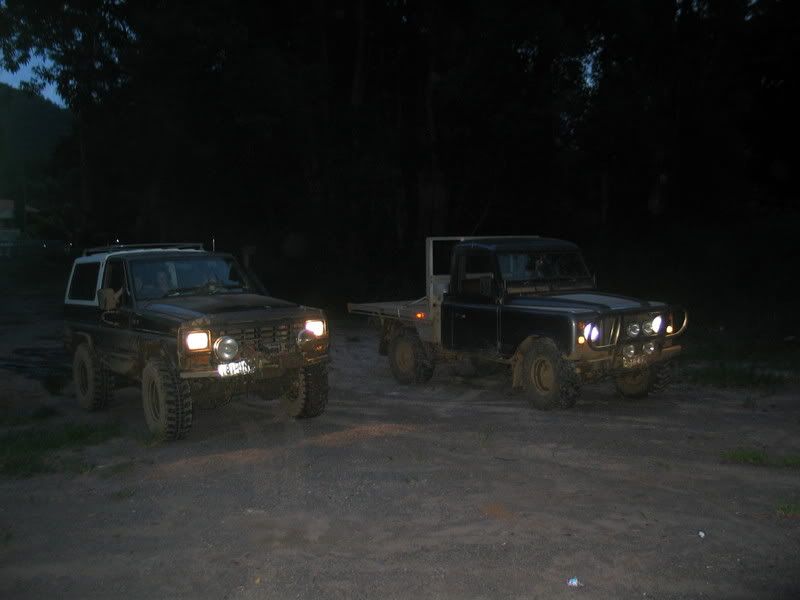
At last I have some more videos to share. 24mins of footage in total, it's not just my car but 3 cars (mine, a rear locked rangie and a twin locked rangie (the one with the lights on the roof)). Enjoy!
Video 1 (10mins) - http://www.youtube.com/watch?v=iNc6gPkiOtE
Video 2 (10mins) - http://www.youtube.com/watch?v=F18Pi1byi-w
Video 3 (4.5mins) - http://www.youtube.com/watch?v=xUGrH6k0JJk
Stirling
Videos:
http://www.youtube.com/watch?v=a8Xljp6DD9g 17 June
http://www.youtube.com/watch?v=_mlJblv9iUo 24 May
& Others!
Videos:
http://www.youtube.com/watch?v=a8Xljp6DD9g 17 June
http://www.youtube.com/watch?v=_mlJblv9iUo 24 May
& Others!
-
stirlsilver
- Posts: 339
- Joined: Tue Nov 21, 2006 9:45 am
- Location: Wheelers Hill, Victoria, Australia
- Contact:
Ok, for those who don't want to sit through 24mins of footage above. I condensed the video down to 7 minutes. Far more user friendly
http://www.youtube.com/watch?v=_mlJblv9iUo
http://www.youtube.com/watch?v=_mlJblv9iUo
Stirling
Videos:
http://www.youtube.com/watch?v=a8Xljp6DD9g 17 June
http://www.youtube.com/watch?v=_mlJblv9iUo 24 May
& Others!
Videos:
http://www.youtube.com/watch?v=a8Xljp6DD9g 17 June
http://www.youtube.com/watch?v=_mlJblv9iUo 24 May
& Others!