Howdy, Names Stirling

Introduce yourself and your vehicles and post (or link to) photos
disco2hse
Posts: 1641
Joined: Sun Apr 27, 2008 3:51 am
Location: Auckland NZ

Post by disco2hse »

Zing. That'd certainly do it :shock:

I think I'll pass on the speedo mount, but I think there's one or two on here that were looking for one :D

One thing on the bright side though. As you say, the damage is confined to that part so doing a swap over should ... No I won't say it and jinx things.

Good luck with the reassembly :)
Alan

1983 ex-army FFR 109 Stage 1
2005 Disco 2 HSE TD5
stirlsilver
Posts: 339
Joined: Tue Nov 21, 2006 9:45 am
Location: Wheelers Hill, Victoria, Australia
Contact:

Post by stirlsilver »

Ok, so the rebuilding has started. I haven't really been bothered updating the last couple of weeks work... mainly because it has been pretty slow going...

From the condition of the main shaft that came out of gearbox 2 (the one in my car) it appeared that the bearing inner race was slipping far less than the one that was in gearbox 1. So using some allthread and some big washers I pulled the bearing out of gearbox 2 and fitted it in to the casing of gearbox 1. I made sure to put some retaining compound so the bearing definitely will not spin inside the case.

Image

After the bearing was inserted and the circlip installed a new oil seal was fitted. Below you can see the condition of the main shaft from gearbox 2.

Image

Image

The shaft was inserted along with the spacer and output gear to check the spacing between the shim and the retaining clip. After checking that the tolerances were acceptable I pulled the mainshaft back out and put some retaining compound on the inner race of the bearing to bond it to the main shaft. The reason this was done was to make sure the bearing will not spin on the shaft ever again. I learnt two pretty valuable lesson from all of this... Without going into the whole story:

1 - Make sure you are quick with the output gear spacer because the shaft ends up with a thin layer of retaining compound which will cause you some grief if it starts set and you don't have the spacer in the right position.

2 - Be careful with the thrust bearing that is between the 1st gear and the main bearing... it can fall off the shoulder on the shaft and get destroyed by your attempst at trying to get the circlip and shim washer on the output gear!! Thankfully I had a spare bearing from gearbox 1 and had to redo the whole operation again after dealing with the dried retaining compound.


Anyway, the shaft did finally go in with the spacer and output gear in the transfer compartment fitted.

Image

Image

Next came the preparation to fit the gearbox 2 selectors into the gearbox 1 case. Before the reverse arm could be fitted, the reverse idler gear needed to be in place.

Image

Image

Because the reverse relay arm pivots on a threaded bolt, there is nothing that can indicate the position of the relay arm on the thread... so by having the idler gear in place you can get a feel for where it should be. When I did it today, I found that 3 exposed threads gave a nice snug fit but not enough to have the brass shoe bottoming out in the idler gear groove (2 threads was too sloppy).

Image

Image

Next the slector shaft and the selectors were fitted. It was pretty straight forward as you will see.

The 1st/2nd selector is placed inside the box.
Image

The 3rd/4th selector is placed inside the box.
Image
Image

The 3rd/4th selector shaft is inserted.
Image

The reverse selector shaft is inserted, while poisitioning the relevant parts along the way.
Image

Image

The 1st/2nd selector shaft is inserted.
Image

Oh, when doing this, make sure you remember to insert the interlocking pins between the selector shafts!

After the selector shafts were finished, the layshaft was dropped in.

Image

This is just a photo of a trial fitment of the input shaft... it looks like I'll need to install the input shaft on to the front bearing plate and then fiddle it into position around the layshaft gear... part of the synchro assembly on the input shaft interferes with the uppermost gear on the layshaft... which is going to be a pain to deal with when fitting the front bearing plate...

Image

Anyway, that's all for now.
disco2hse
Posts: 1641
Joined: Sun Apr 27, 2008 3:51 am
Location: Auckland NZ

Post by disco2hse »

Stirling I think you are enjoying this way too much. :D

You know this will provide years of entertainment value for dedicated LT95 supporters for years to come. Certainly reading the workshop manual is nowhere near as interesting. ;)

Good stuff mate.
Alan

1983 ex-army FFR 109 Stage 1
2005 Disco 2 HSE TD5
V8_Disco
Posts: 118
Joined: Tue Mar 03, 2009 1:10 pm
Location: East Yorkshire

Post by V8_Disco »

realy inspiring, I would like to do this for mine at some point, add an overdirive and put the right speedo gear in

A
1982, Stage 1 SW LPG
1999, Disco 2 4.6 Stage 1 Heads ES Multipoint LPG
1976, 88 SW
1973, 88 Truck Cab
disco2hse
Posts: 1641
Joined: Sun Apr 27, 2008 3:51 am
Location: Auckland NZ

Post by disco2hse »

Adding an overdrive is not hard, just expensive ;)
Alan

1983 ex-army FFR 109 Stage 1
2005 Disco 2 HSE TD5
V8_Disco
Posts: 118
Joined: Tue Mar 03, 2009 1:10 pm
Location: East Yorkshire

Post by V8_Disco »

Alan, Indeed but while I have it appart I would like to overhaul the box, replace the speedo drive (I have RR gearing) and a new Clutch

A
1982, Stage 1 SW LPG
1999, Disco 2 4.6 Stage 1 Heads ES Multipoint LPG
1976, 88 SW
1973, 88 Truck Cab
stirlsilver
Posts: 339
Joined: Tue Nov 21, 2006 9:45 am
Location: Wheelers Hill, Victoria, Australia
Contact:

Post by stirlsilver »

Alright, so I'm back from the christmas holidays and I got back in to getting this gearbox back together.

Sorry about the rubbish photos... I had to use my mobile phone this time.

It was all going along reasonably smoothly until I ran into some problems with the 4th gear syncro... anyway you will find out more when I get to that point.

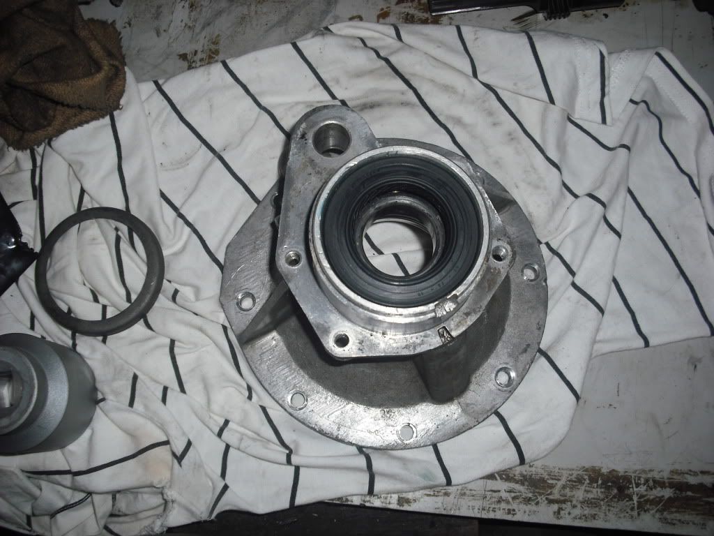
I had fitted the layshaft into the box and positioned the front cover on the gearbox. I installed the gasket dry here (although i'm pretty sure that wasn't correct and I do address this later).

Image

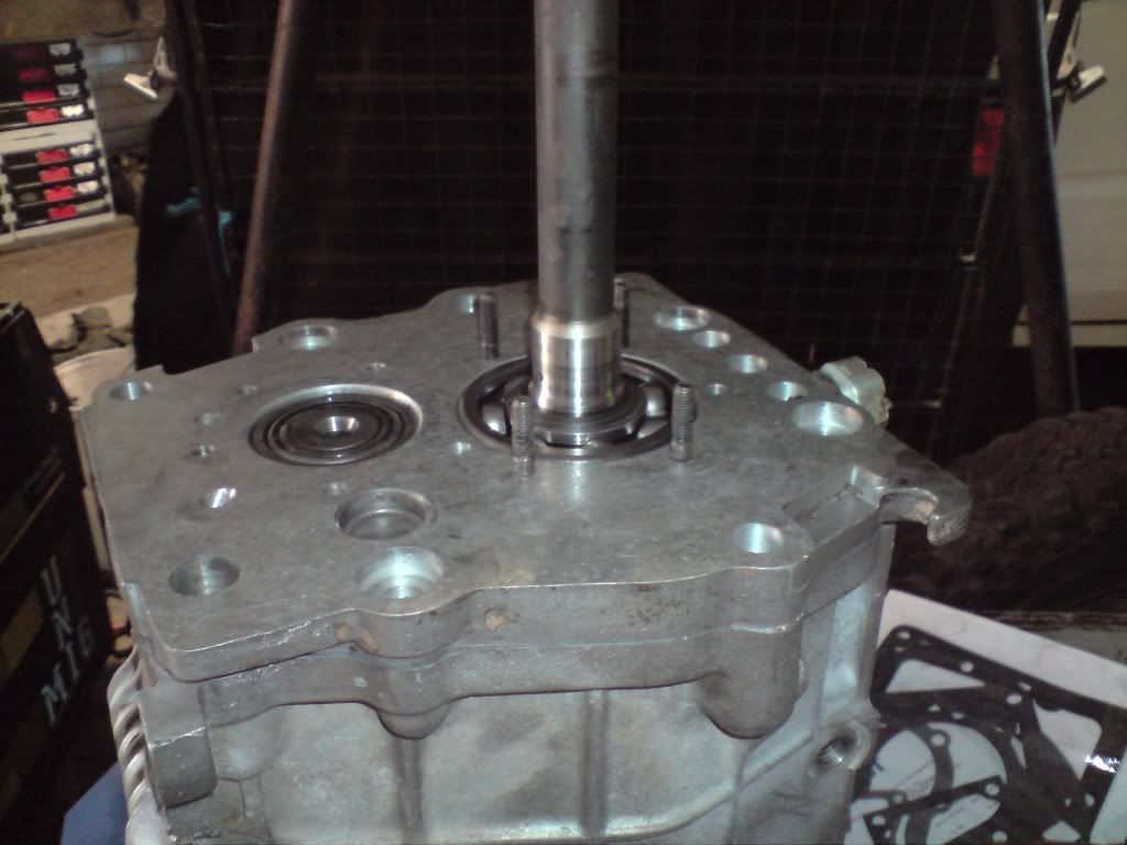
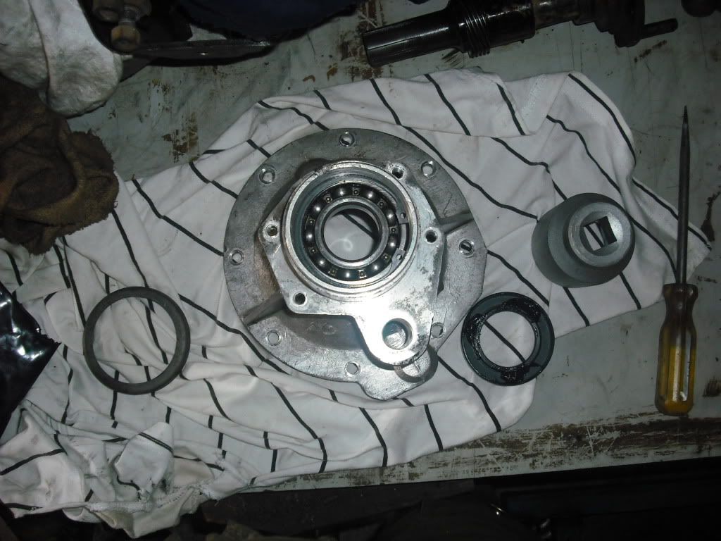
I pulled out the oil feeder ring that sits around the input shaft and changed the input shaft oil seal. No major issues there the bits come out fairly easily. After that I bolted the assembly on to the gearbox front cover (again I used a dry gasket, pretty sure that wasn't right, more later).

Inserted the oil pump gears and the oil pump cover gasket (again dry...)

Image

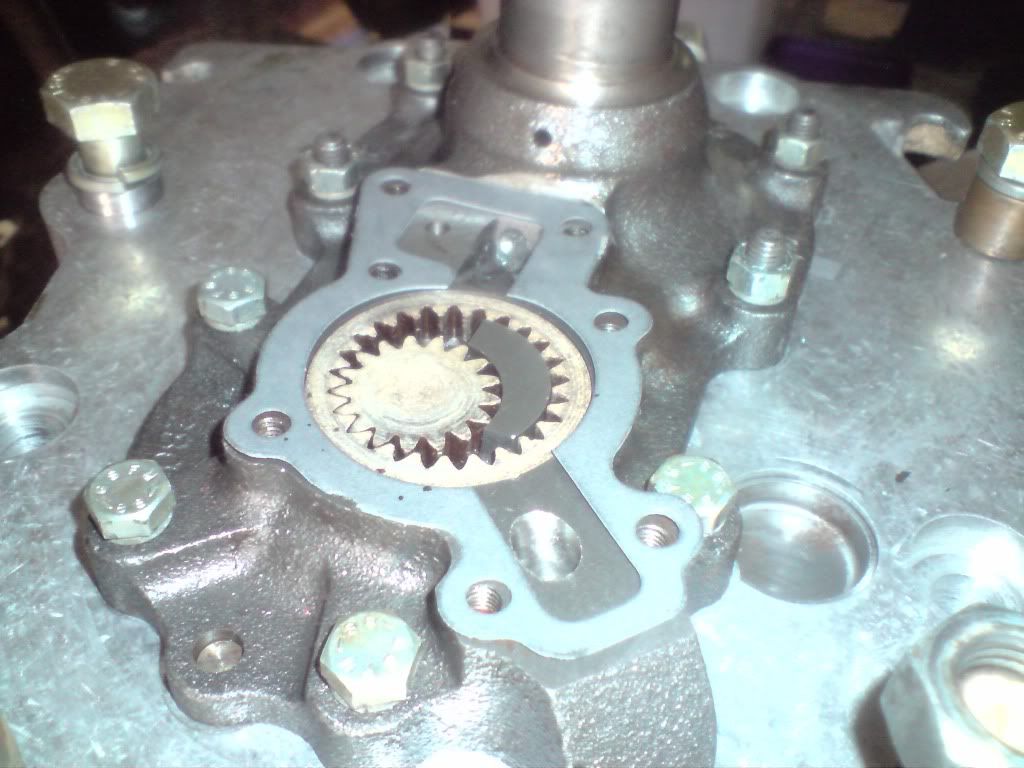
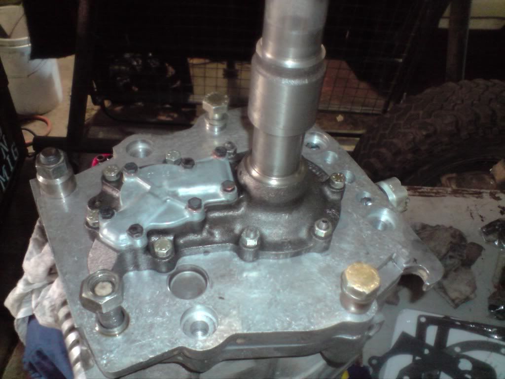
I poured in a little oil around the pump to make sure nothing was dry and bolted on the cover.

Image

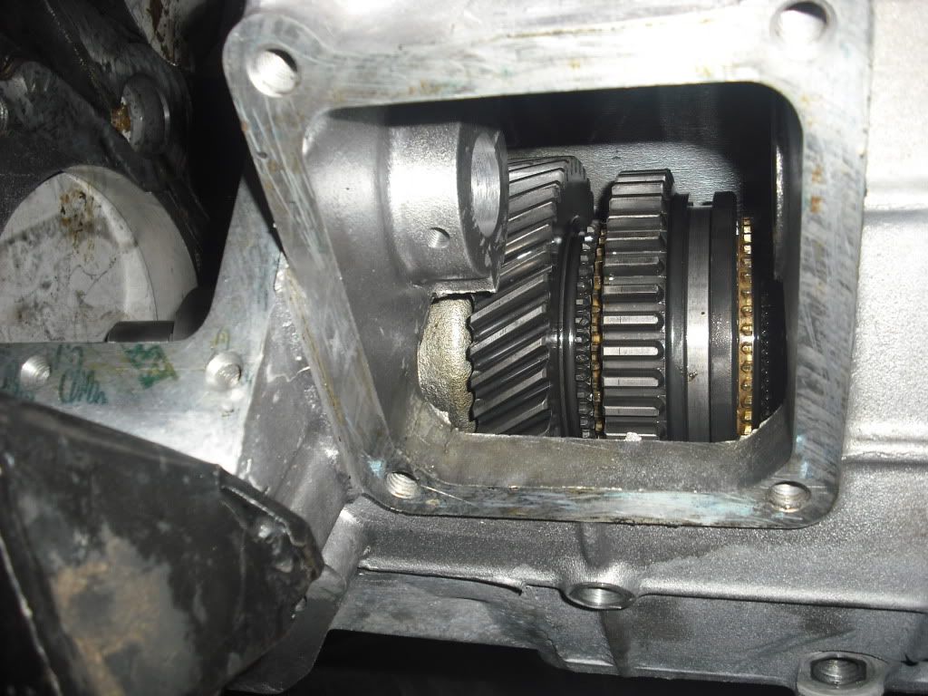
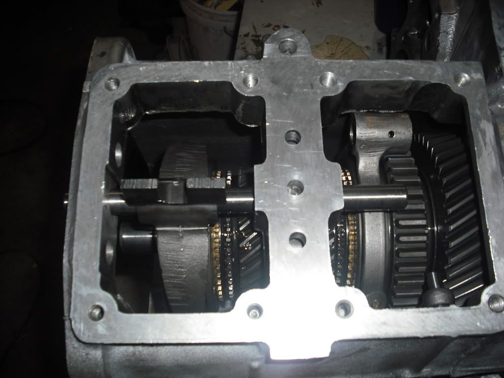
After this point I decided to tip the gearbox over and just check to make sure all I can engage all the gears... 1st and 2nd was fine, reverse, fine 3rd and 4th.... stiff, anyway I eventually got it to engage 3rd gear and then on peering inside the case I saw the brass syncro cone sitting an an angle with one of the detent ball retaining plates poped out!! So it was now stuck in 3rd gear.

After a bit of cursing I just put a cover over it and went home to get over the fact that I had to pretty much pull everything out of the box to fix the problem...


Alright next day, Pulled the oil pump out, took the front cover off (which again required me to tap out the input shaft from the bearing, followed by removing the lay shaft.

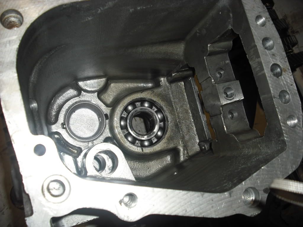
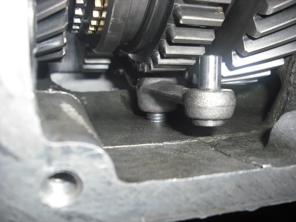
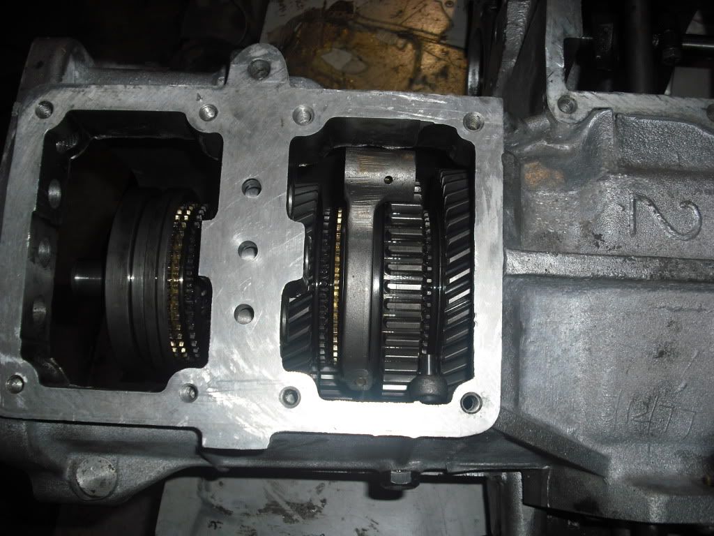
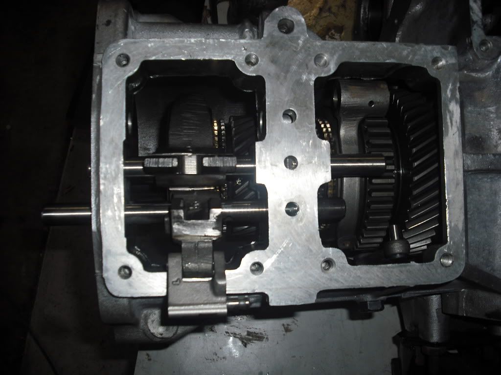
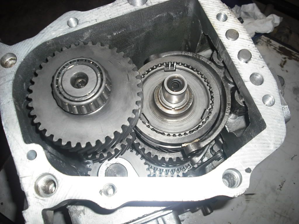
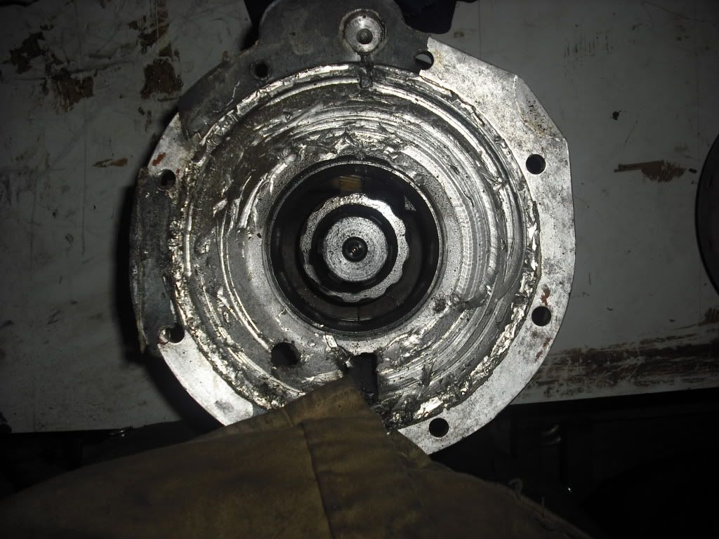
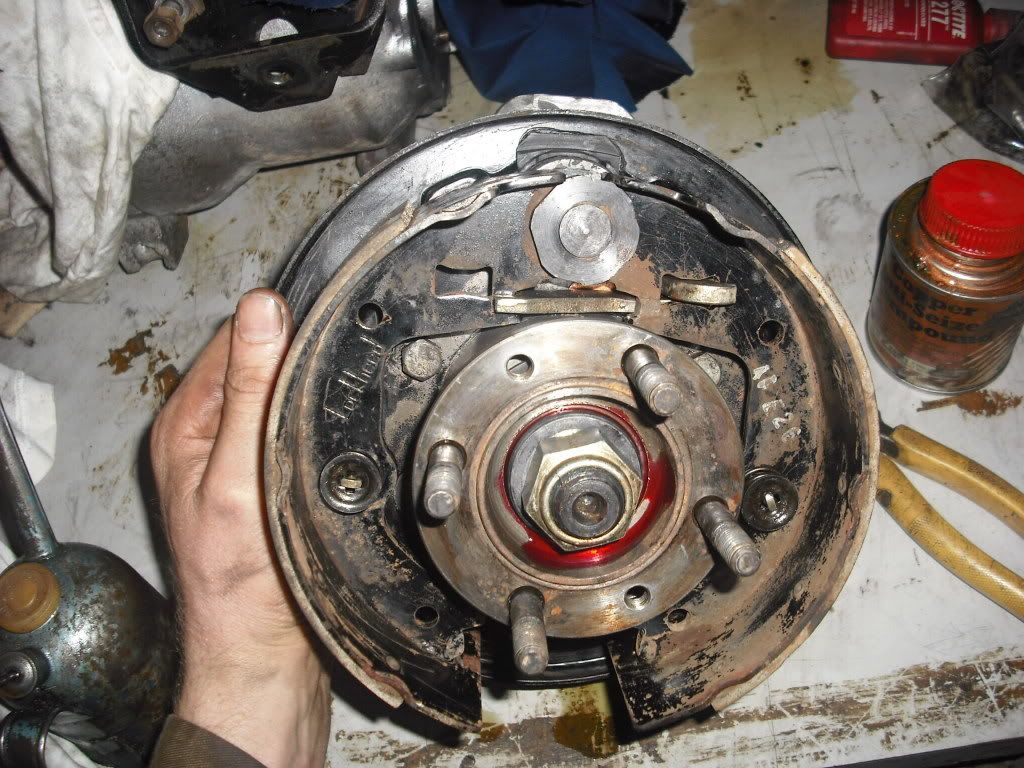
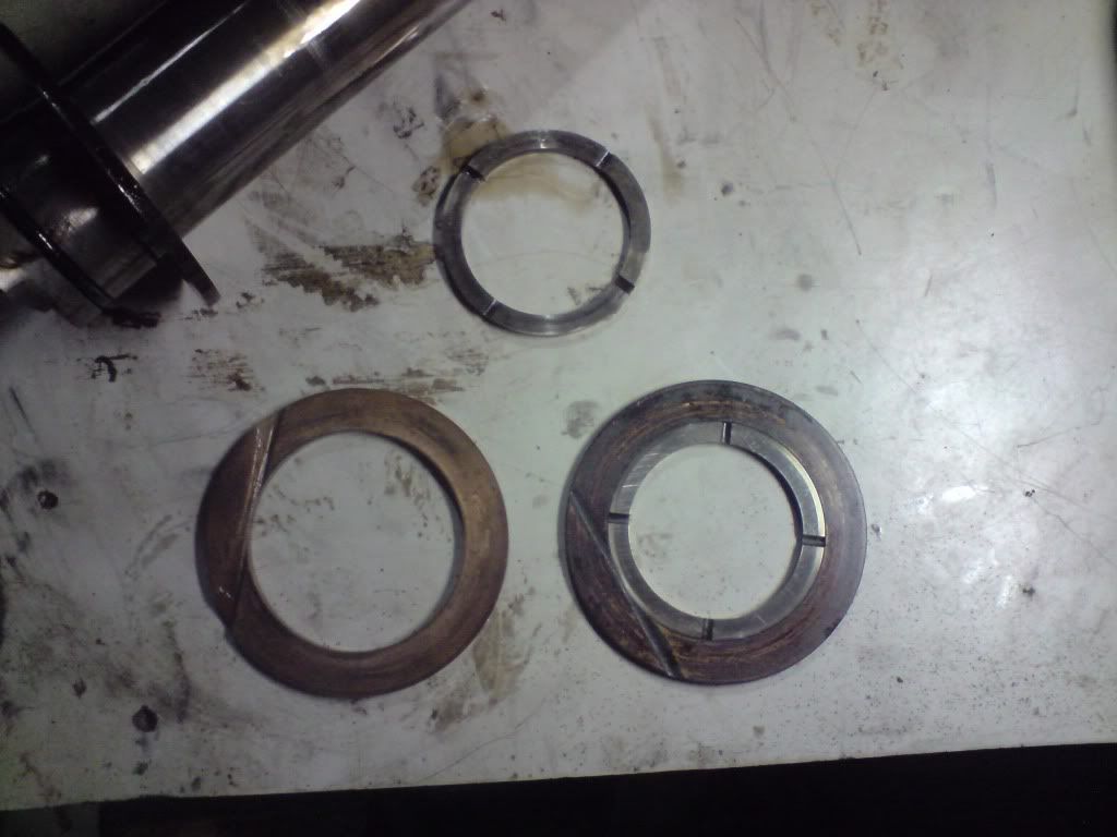
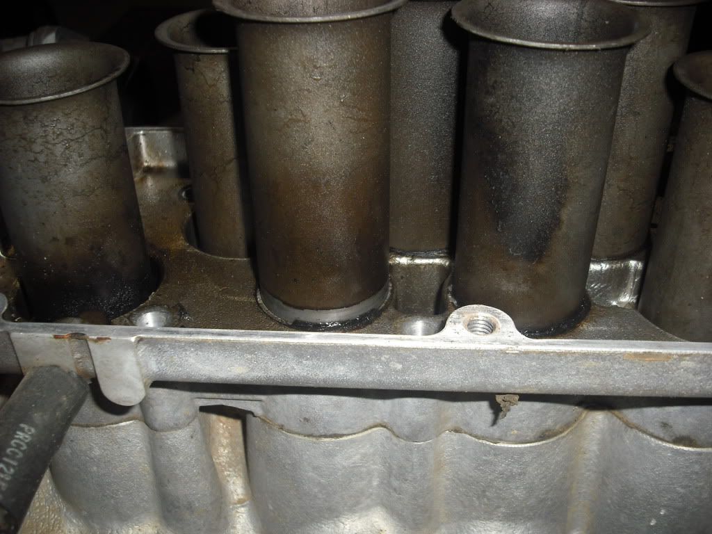
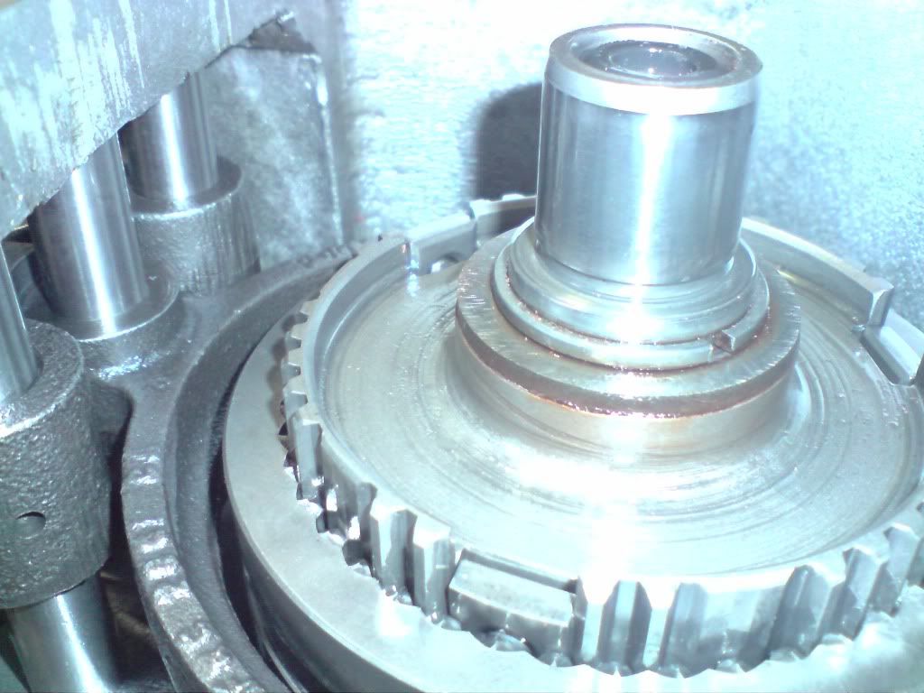
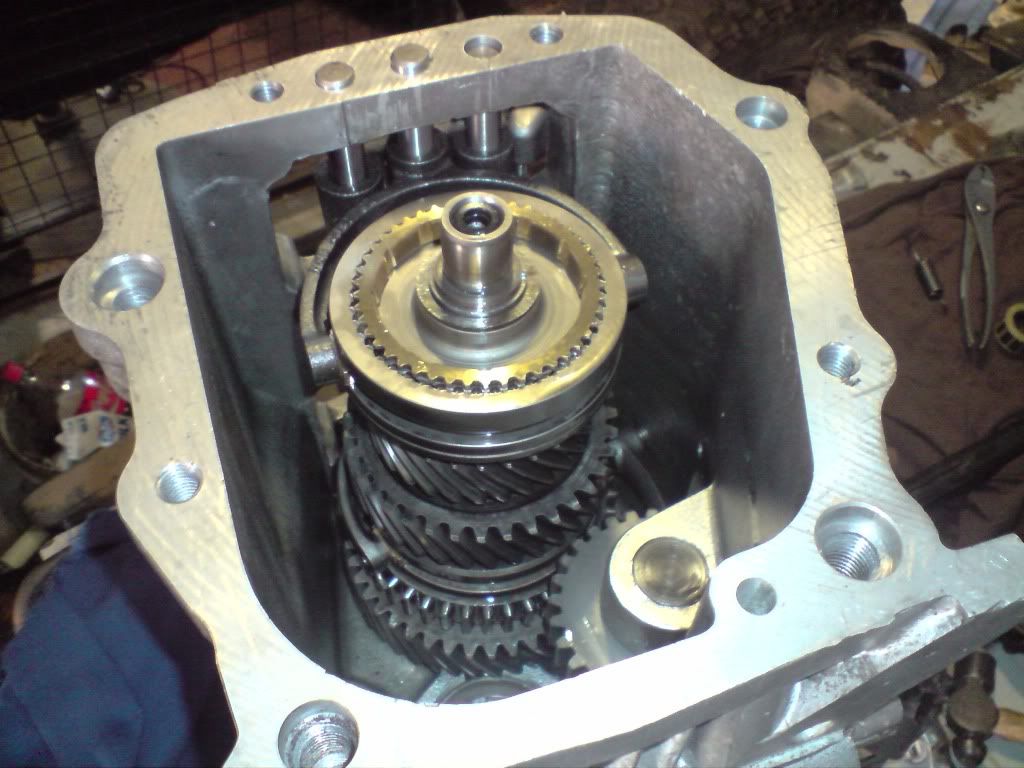
Photo below shows the culprit. See the exposed detent ball on the far left? It shouldn't be poped out should be like the one on the far right.

Image

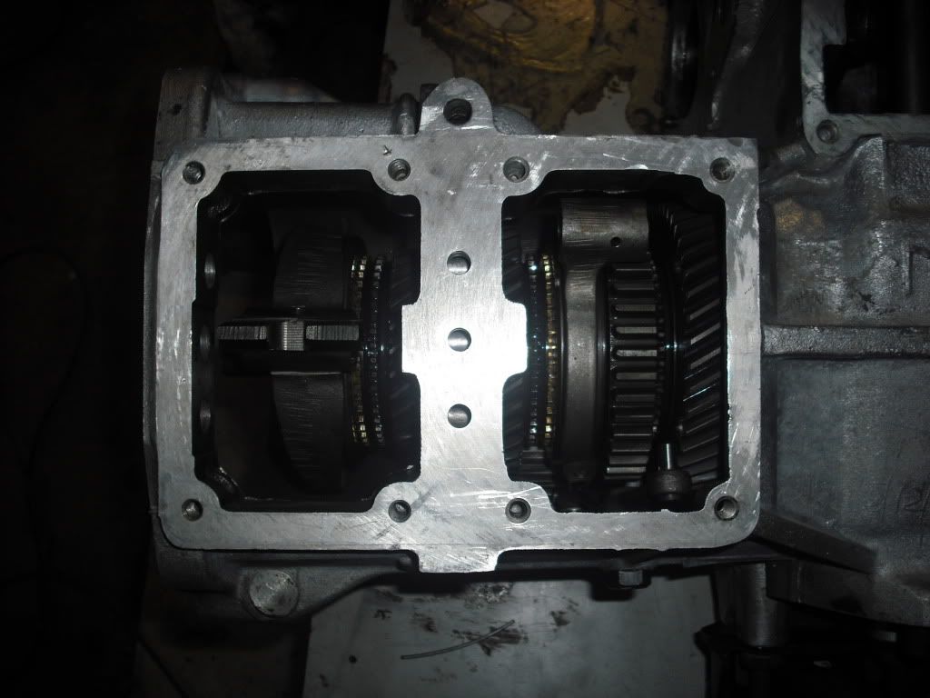
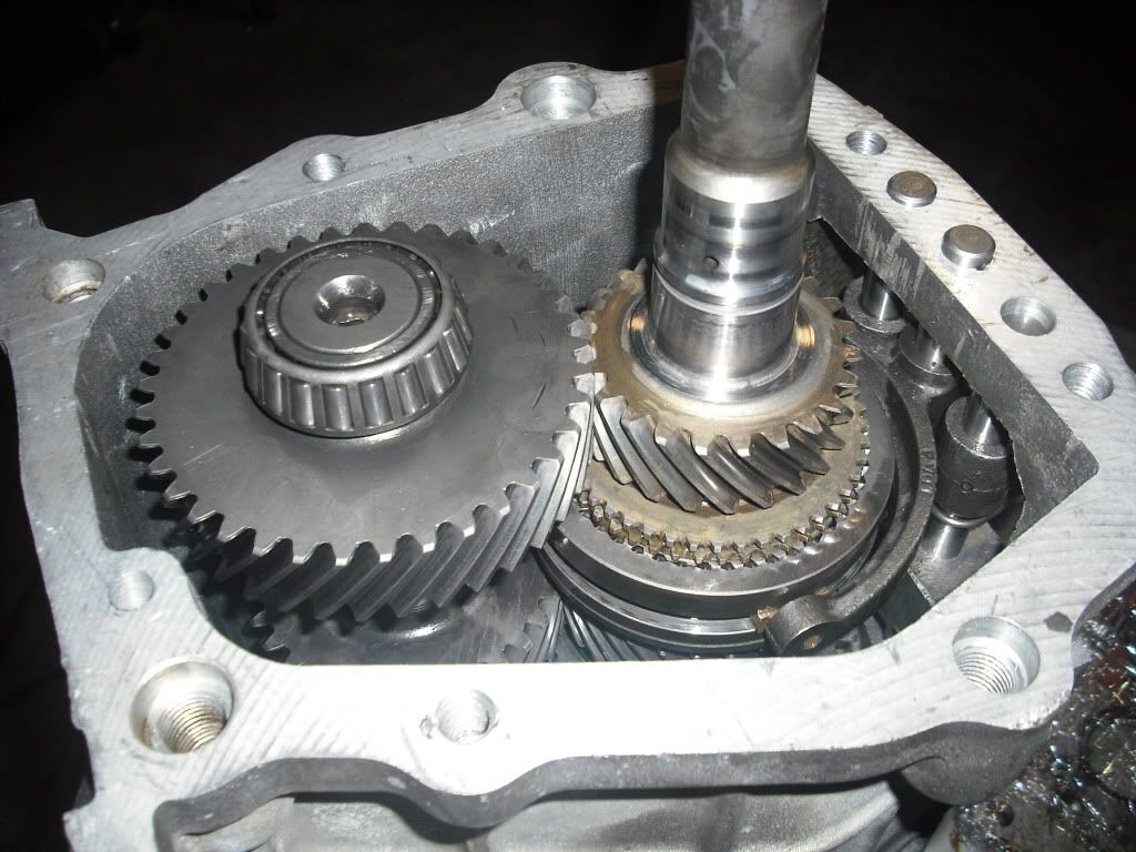
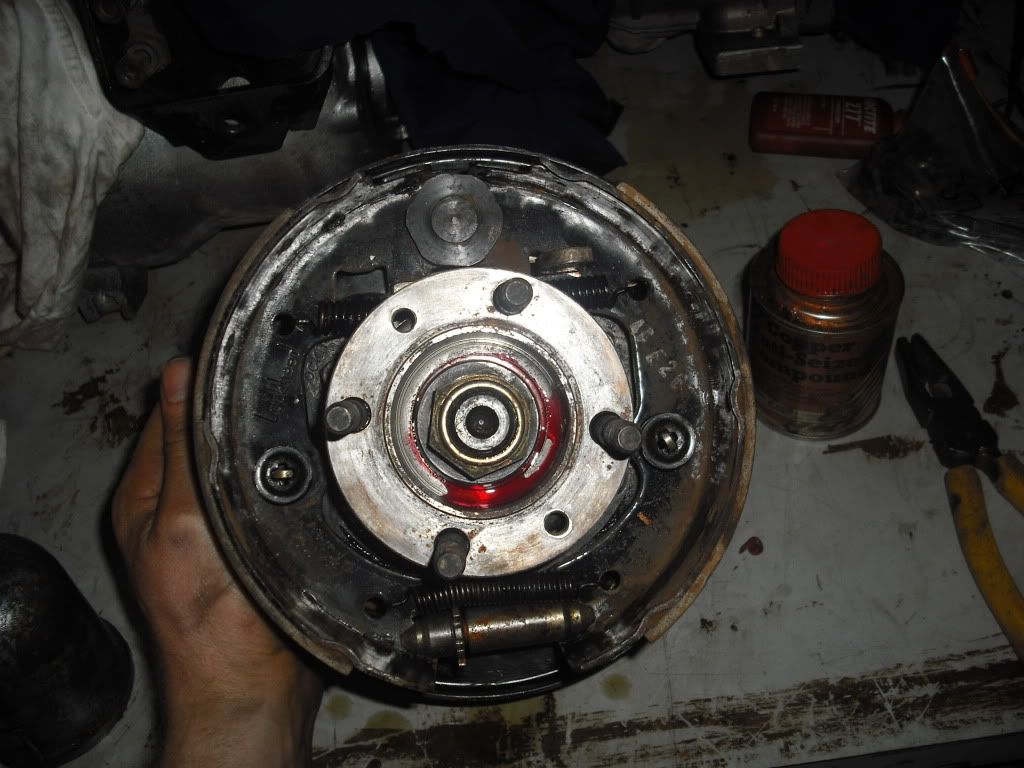
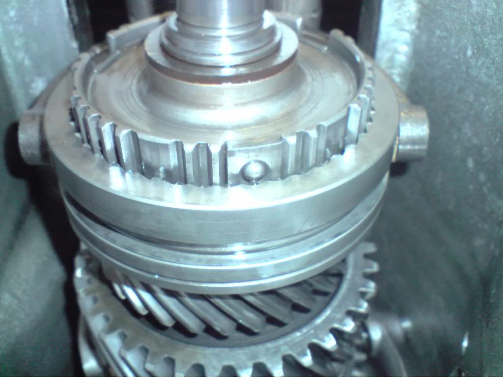
Here is a better view, This is what it shouldn't look like when 3rd gear is selected...

Image

I then realised that in order to get the 3rd/4th selector for off I had to pull ALL the other slectors out too!! Anyway, I got over it... eventually and got on with it

So after fooling around with the rediculously hard snap ring holding the 3rd/4th gear selector assembly in place I managed to pull the assembly out and dismantle it. Just a tip - you might want to mark the orientation of the inner and outer assemblies relative to each other because the tolerances are very small and it simply won't go in if they aren't reassembled the same way they are pulled appart... I later ended up resorting to looking for the wear marks from the detent balls to figure out the orientation!

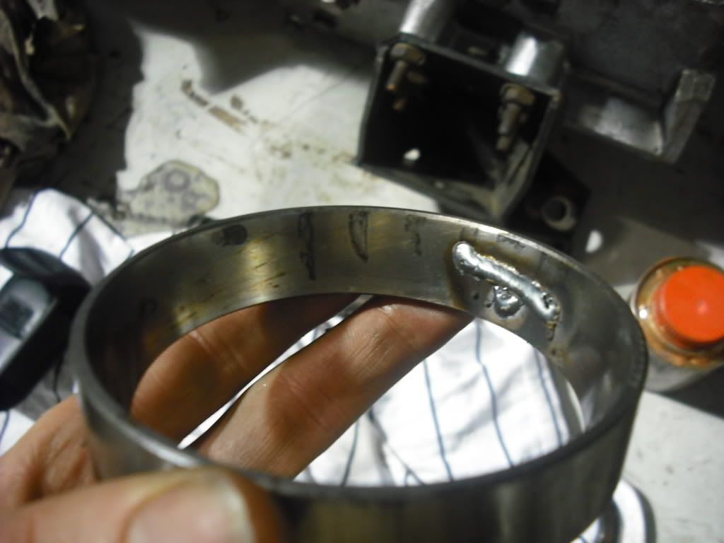
Anyway, the culprit!

Image

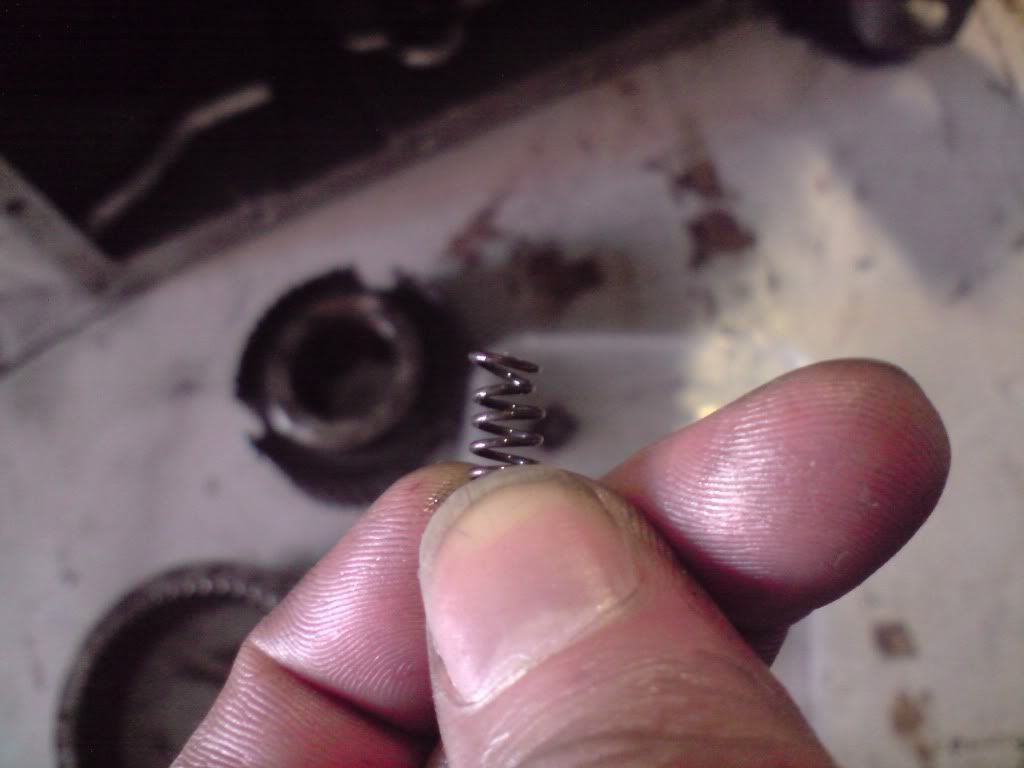
This was caused by sliding the 3rd/4th collar in to 4th gear when the rest of the assembly wasn't there to prevent the plates with the detent balls slipping out. I didn't know this at the time and I ended up mangling 2 of the 3 springs!

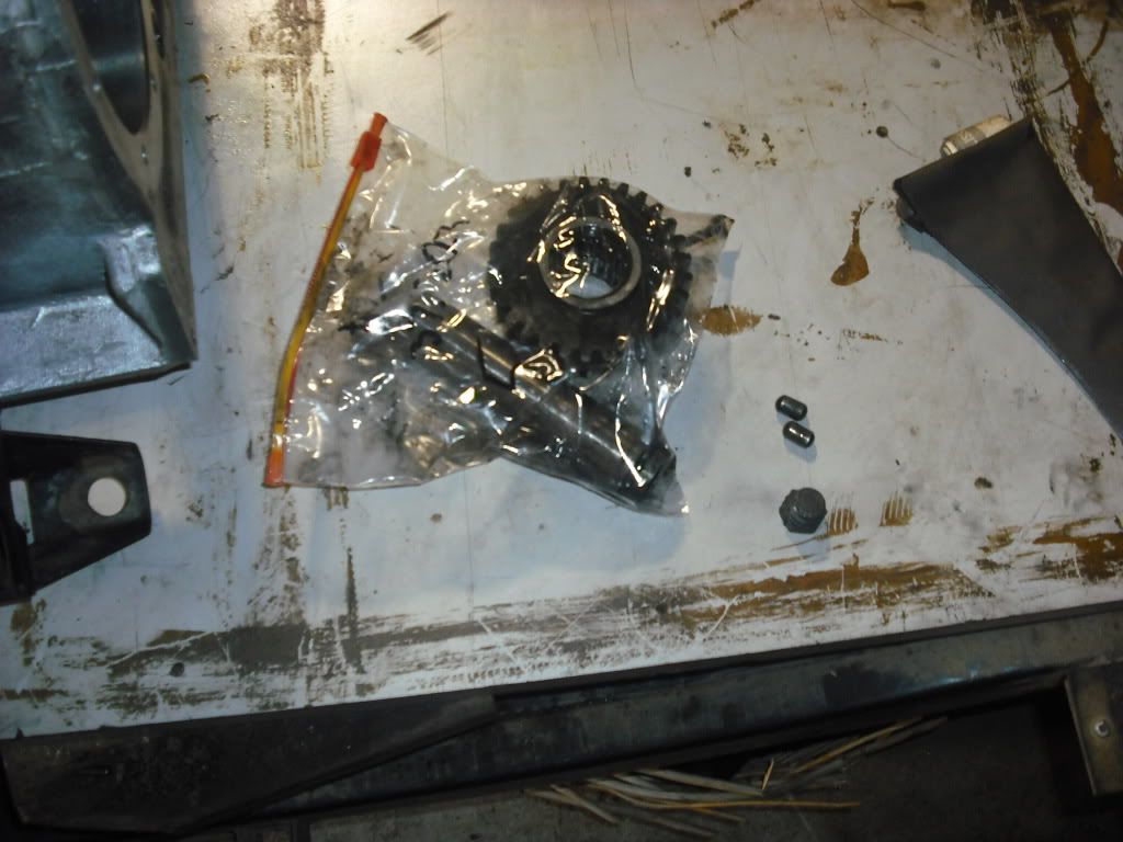
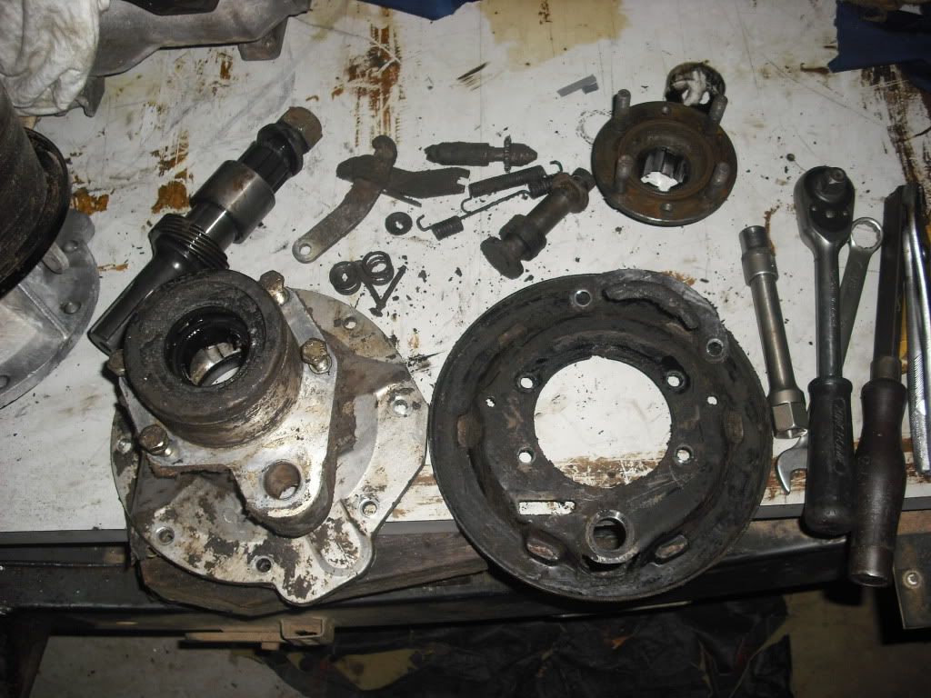
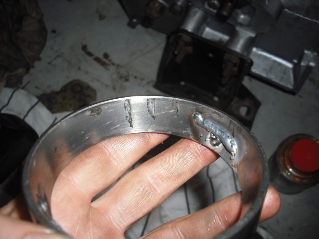
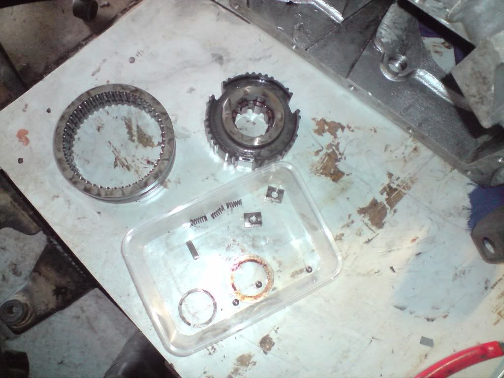
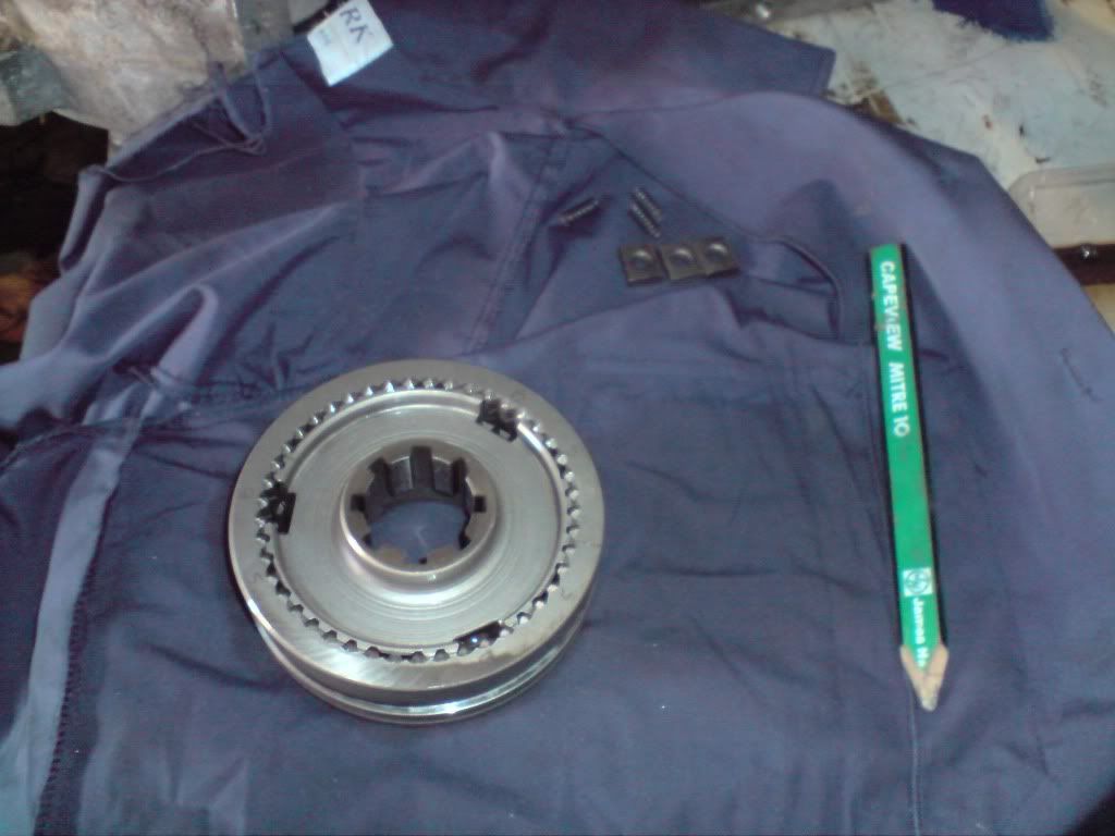
Just a photo of all the bits that make up the selector assembly. Along with the shim and snap ring that holds the assembly on the shaft.

Image

The whole assembly cleaned... there was a bit of sludge actually. Like I said earlier, the pieces wouldn't go together unless they are put back together the way they came apart.

Image

After scavenging springs from gearbox 1 I managed to get the detent balls and blocks back in to place... a pretty fiddly task when you do it by hand because some times the balls would slip out and shoot off!

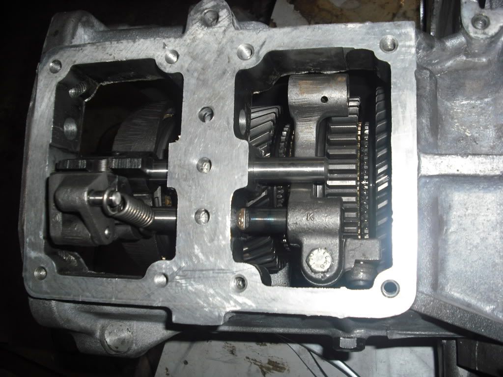
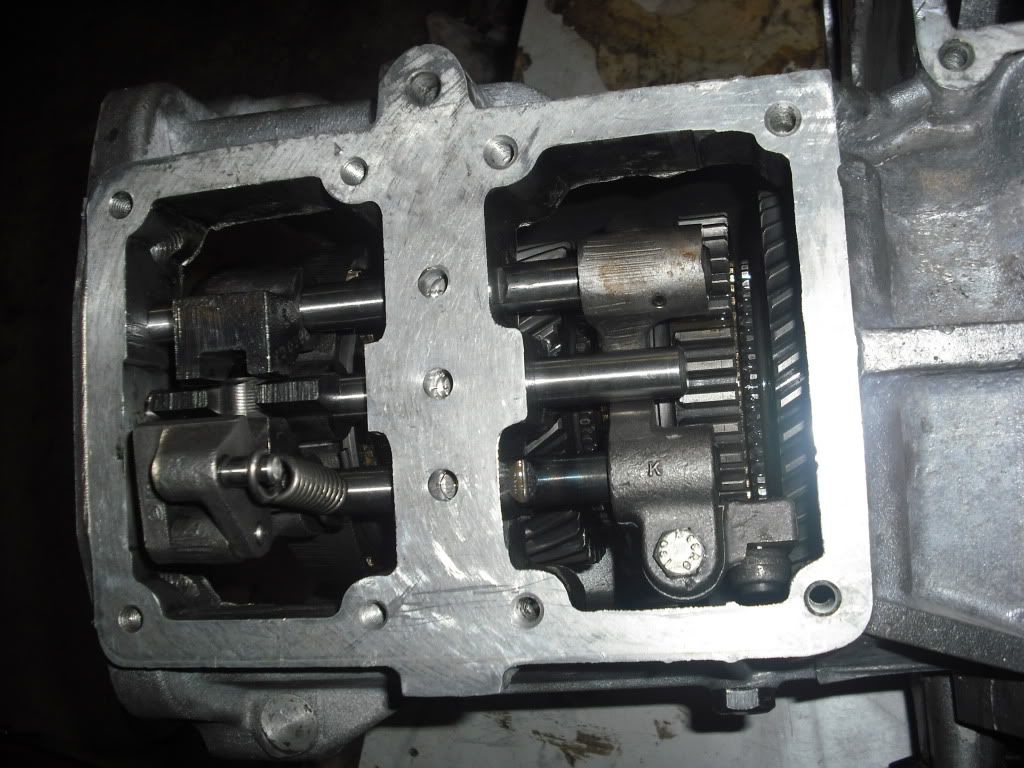
I installed the assembly back in to the box, sat a brass syncro ring in place to ensure the plates wouldn't slip out again and fitted all the selector forks and shafts... again.

Image

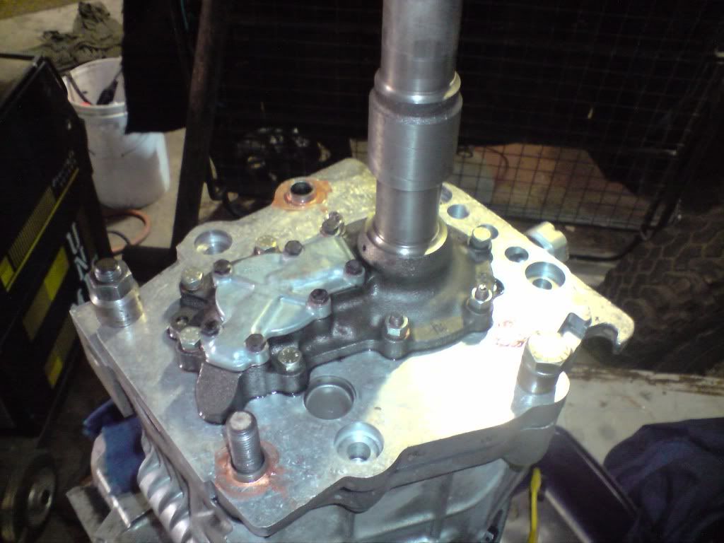
As I was doing this a second time round I figured I would show how I put the layshaft and front cover back on to the gearbox.

First install the input shaft into the input bearing and install the shim and circlip.

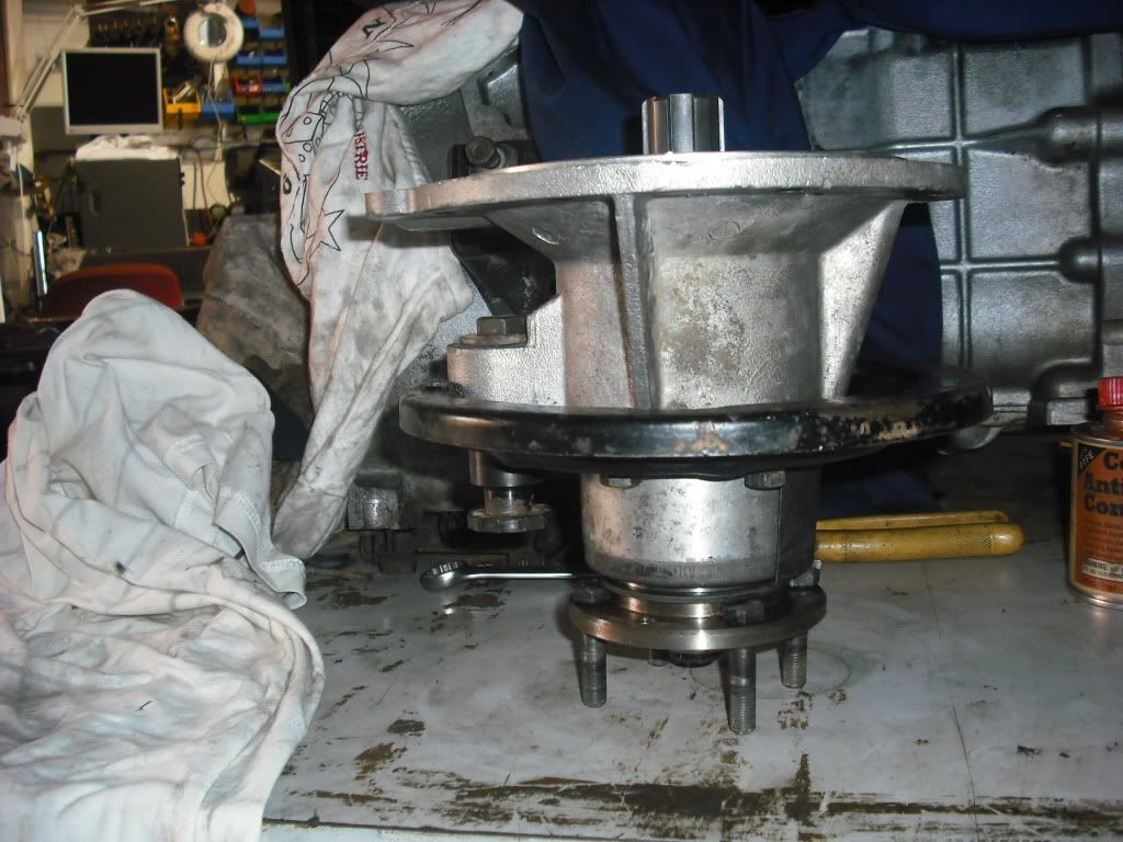
Hold the layshaft in a vice. Input side up.

Image

Fit the front cover on to the lay shaft, you can sort of angle them on and then slip the bearing into the outer race... it only JUST fits in. You can't get the fit the front cover on with the layshaft in the box... that is for sure.

Image

Image

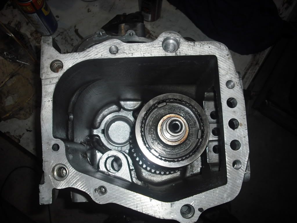
I installed the front cover... this time with the gasket soaked in oil. The reason I did this is because I noticed the gaskets were fibre and the oil soaked in very very easily. When I had installed them in dry the first time I noticed that they leaked over night!

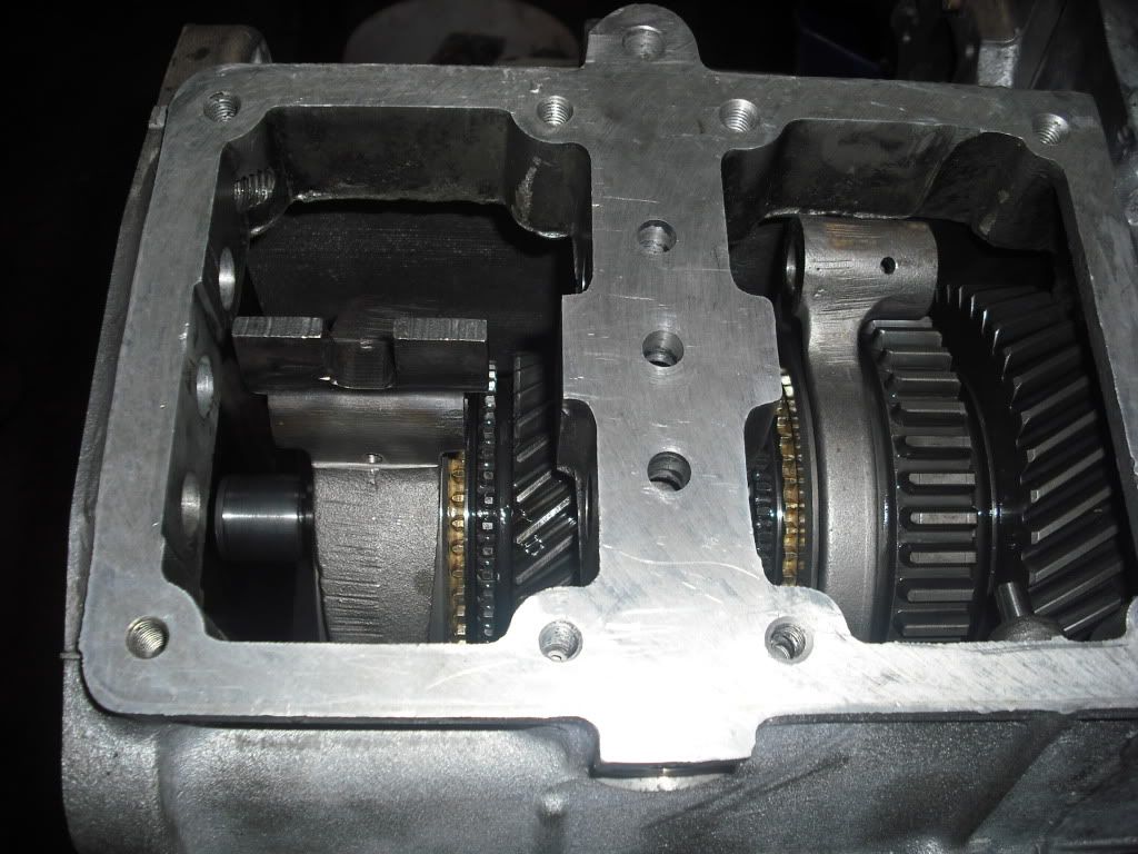
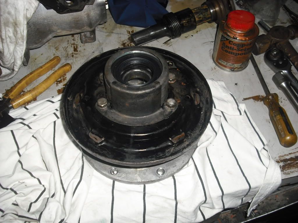
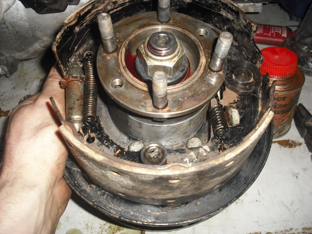
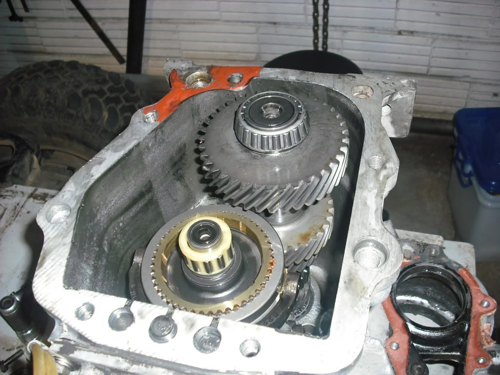
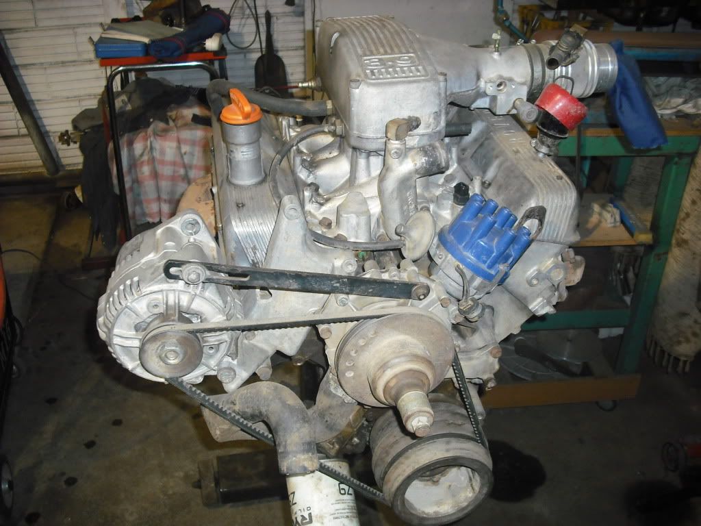
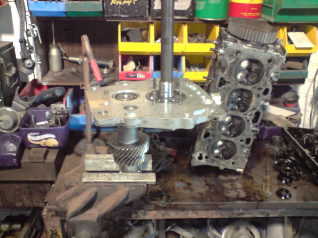
Anyway, below you can see the gearbox back to where I had it the day before... so a full day of work just to sort out that 4th gear synchro issue...

Image

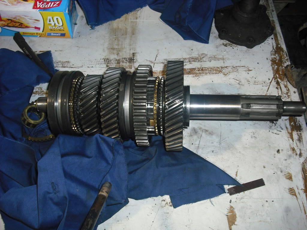
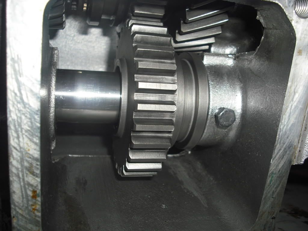
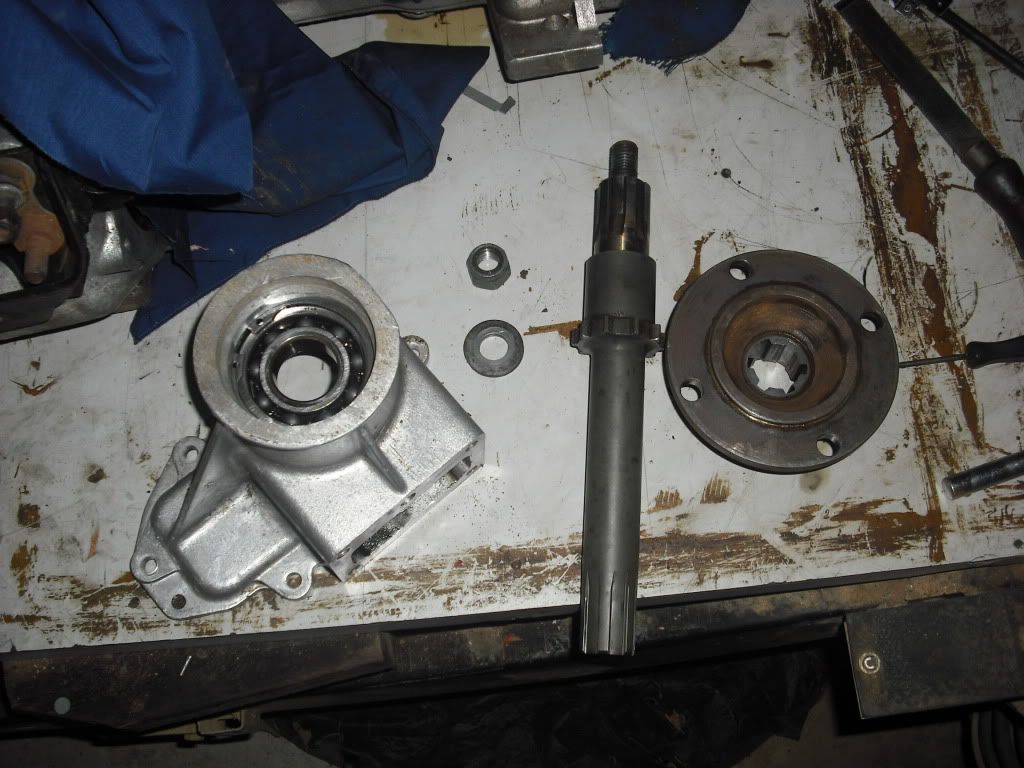
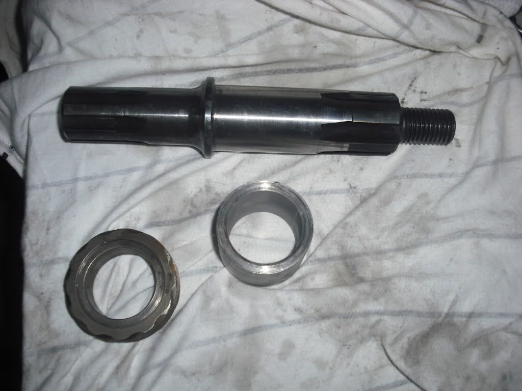
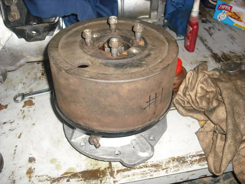
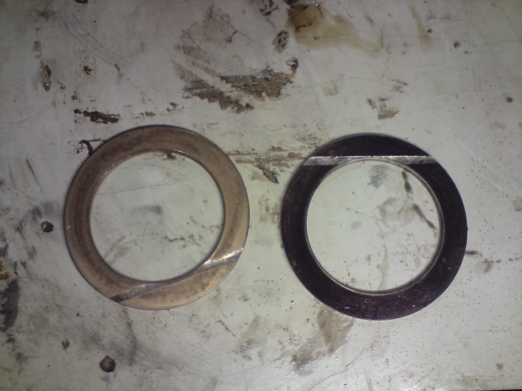
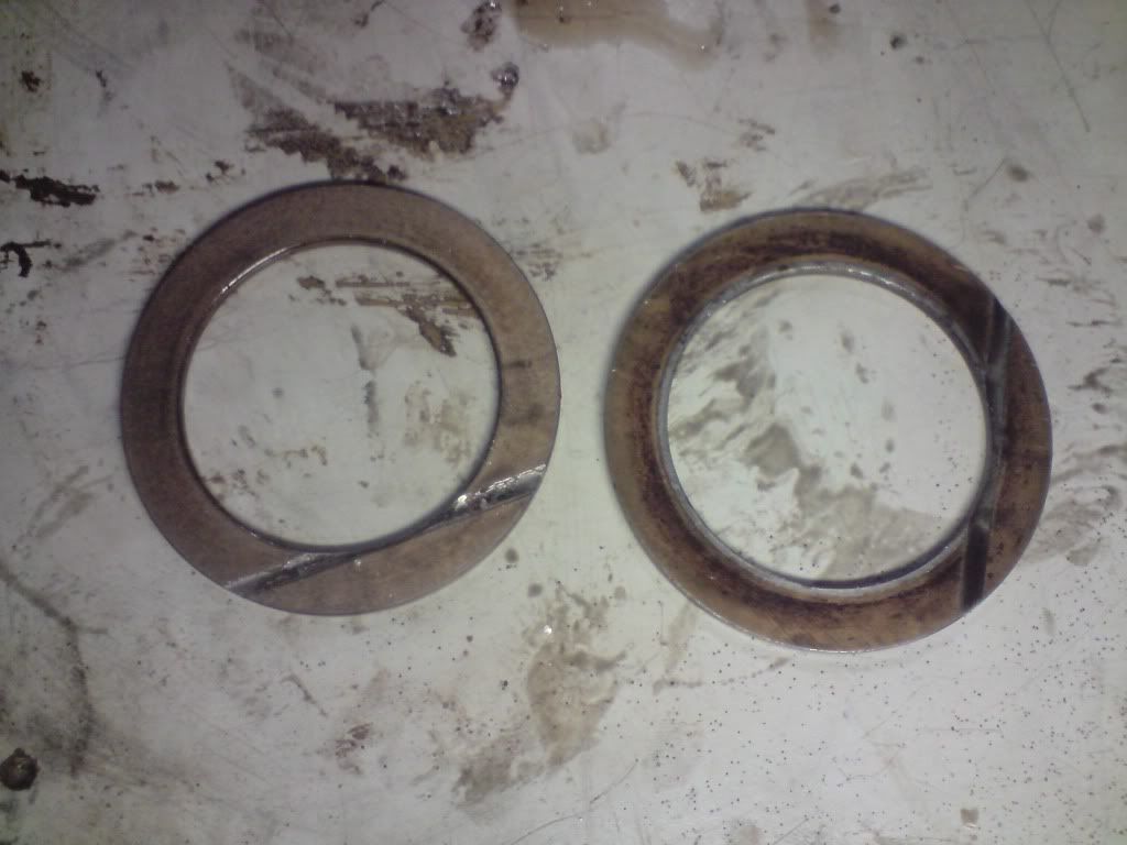
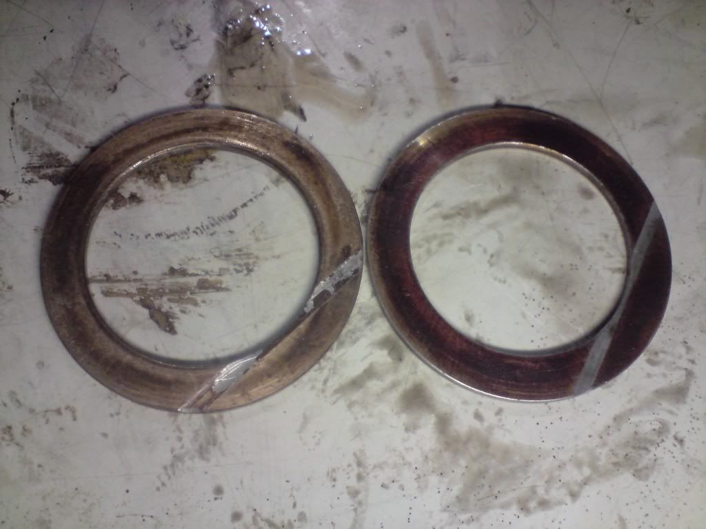
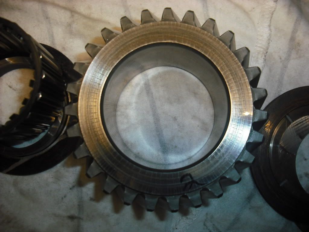
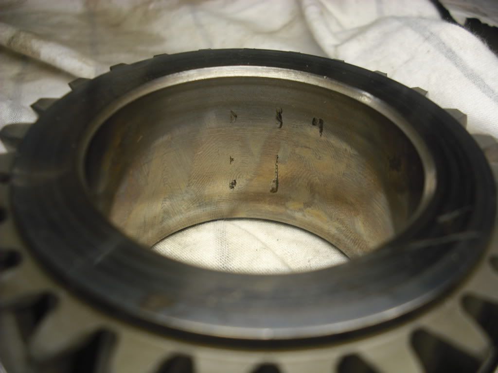
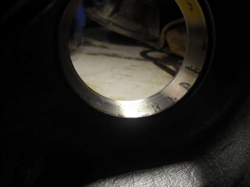
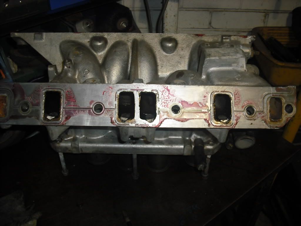
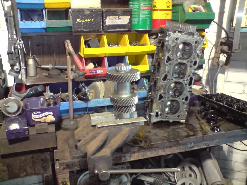
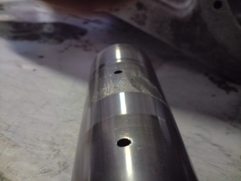
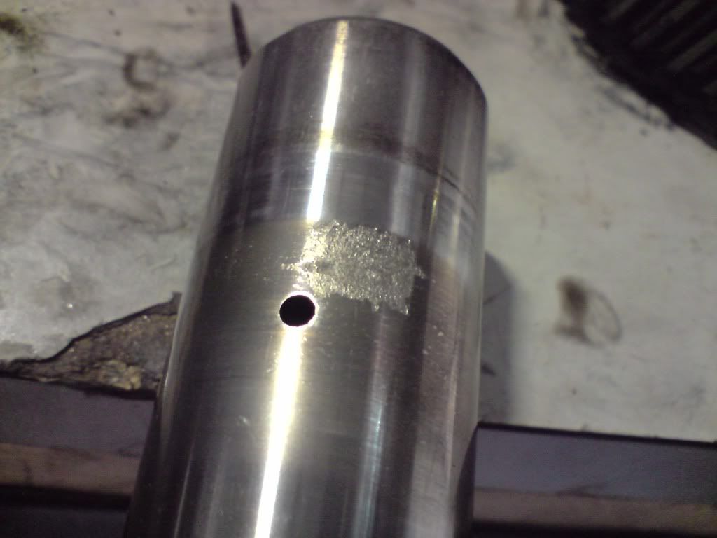
I started looking into assembling the transfer case, I was considering installing the intermediate shafts in the transfer case... but I found very bad wear marks on both the intermediate shafts. Below is the shaft that came out of the box I dismantled (box 1)

Image

Image

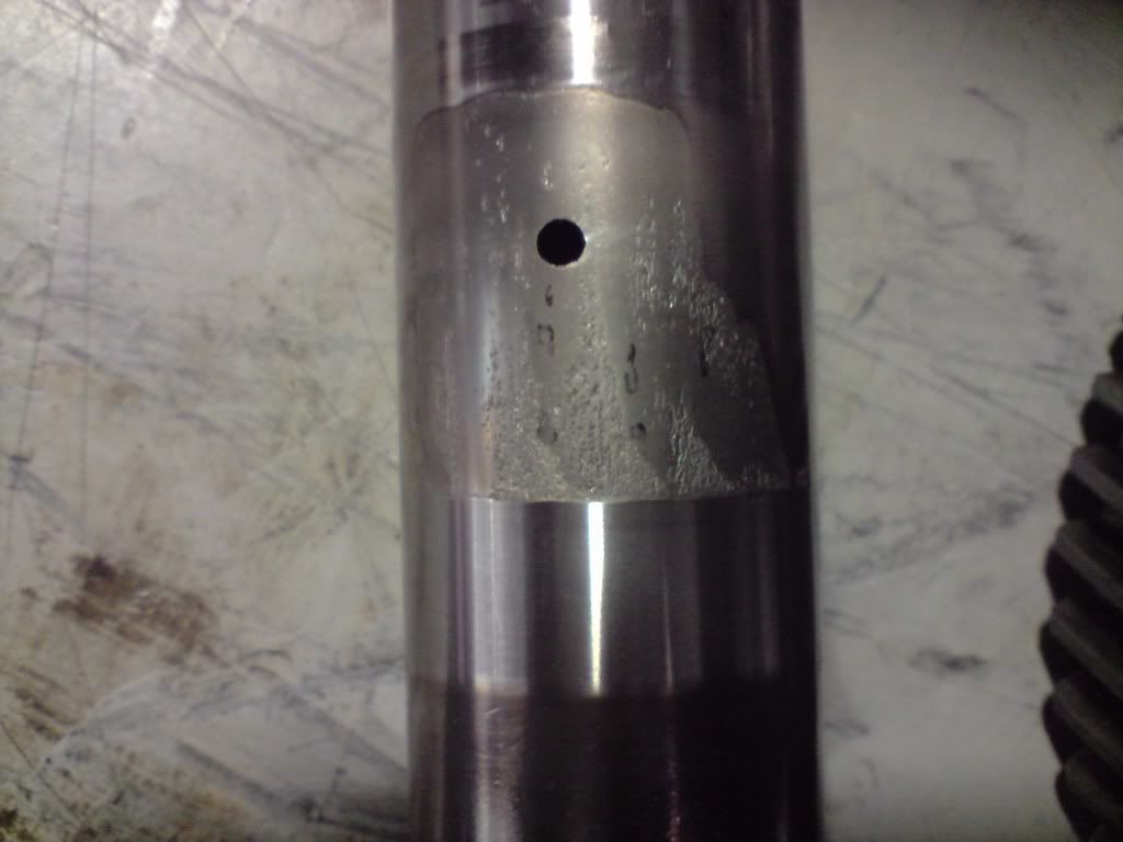
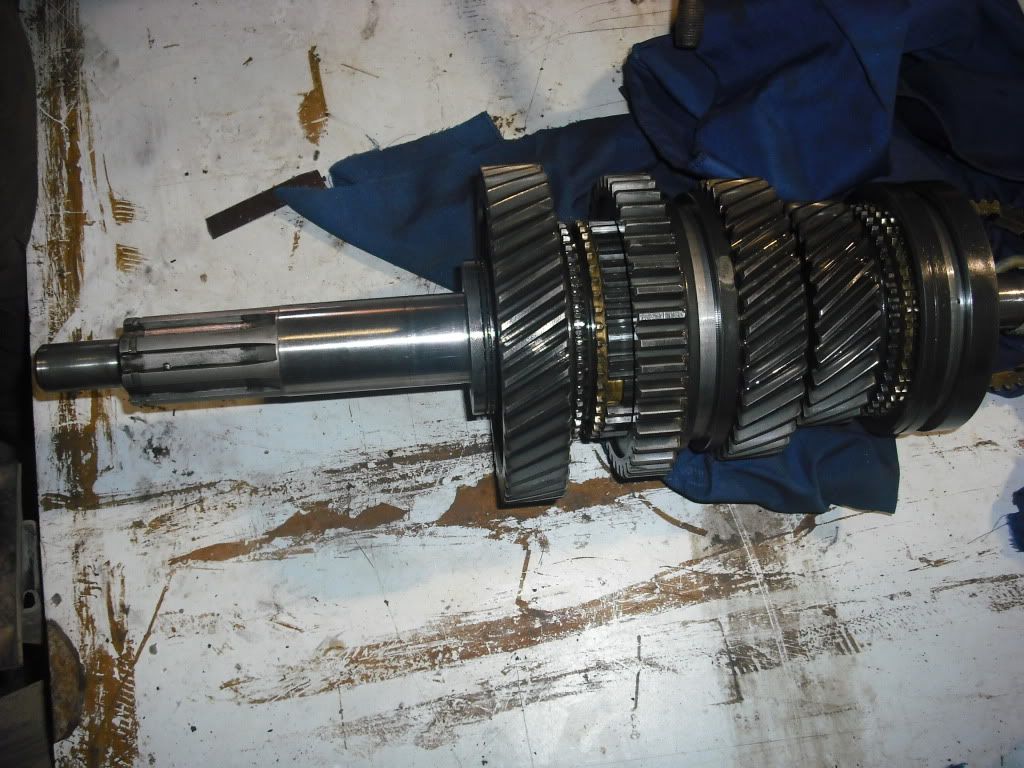
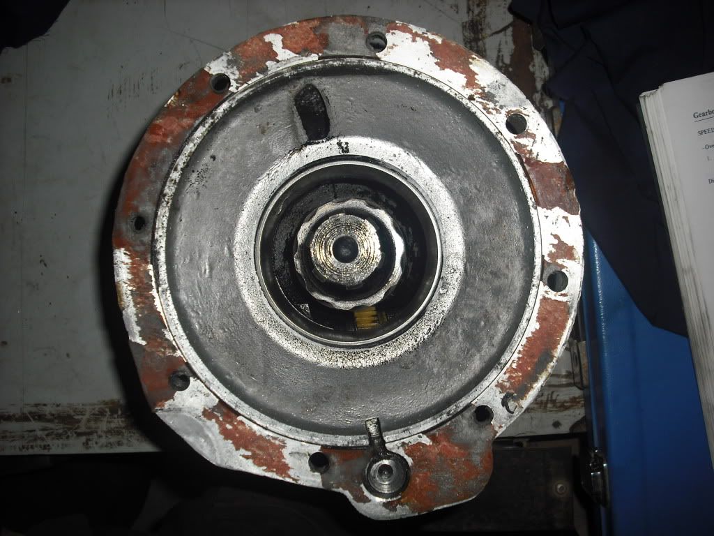
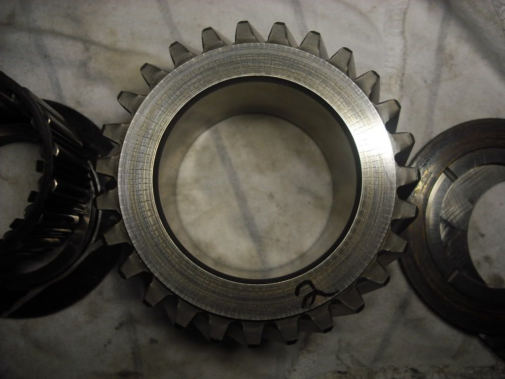
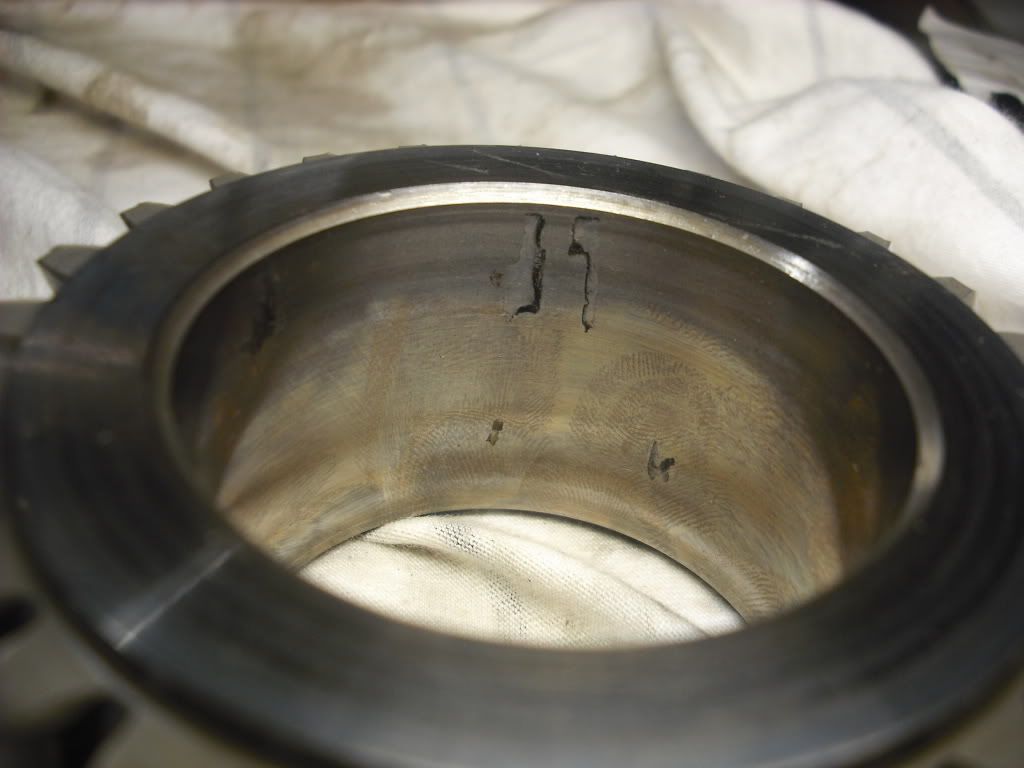
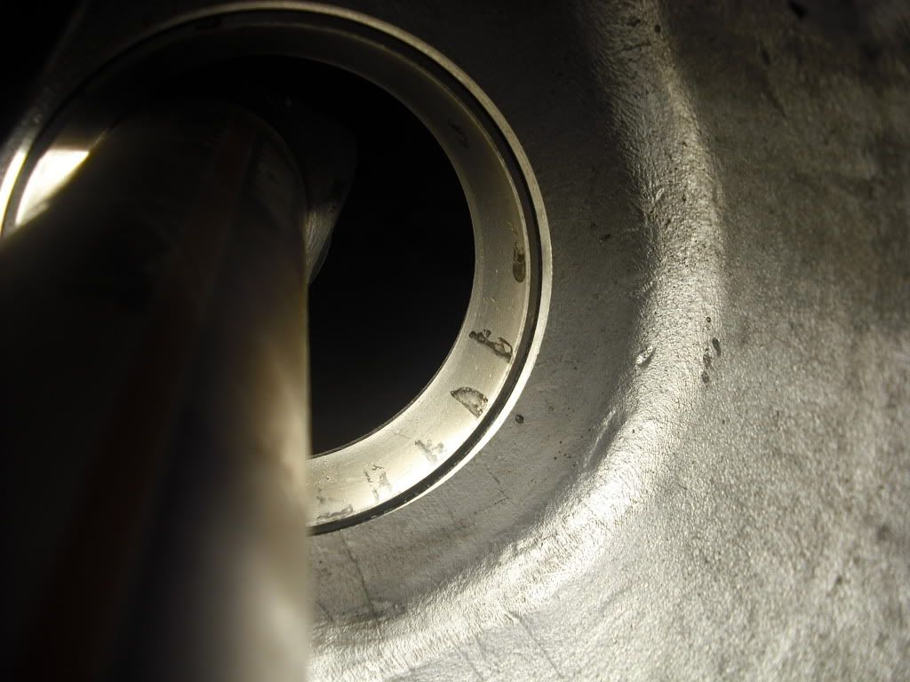
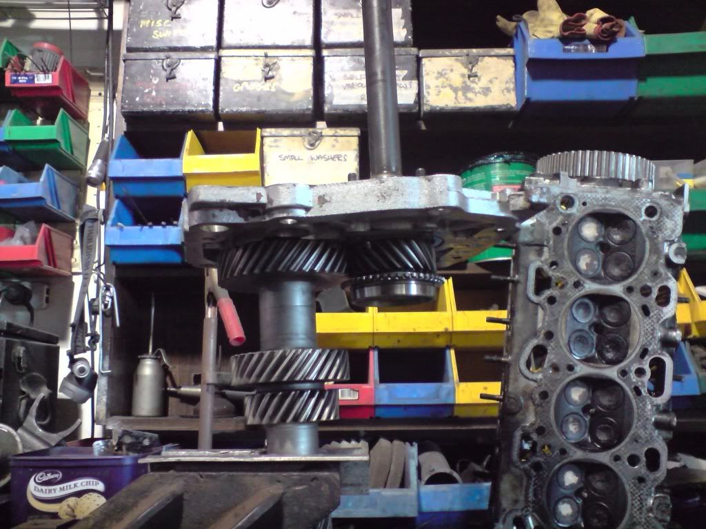
Blelow is the one that came out of my car... better but still no good... The wear marks on both were on the high range gear side.

Image

Image

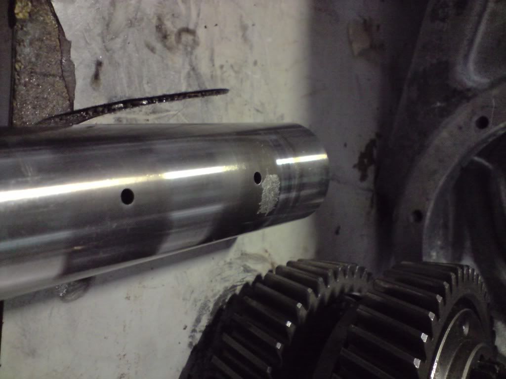
So that is where I am at... I think i'm going to have to try and find an intermediate shaft... anyone have one kicking around by any chance??
disco2hse
Posts: 1641
Joined: Sun Apr 27, 2008 3:51 am
Location: Auckland NZ

Post by disco2hse »

I wonder if the wear is because the boxes have been run without sufficient oil in them at some point, or if they have been run at very high temperatures.

Have you though about putting an oil cooler in it?
Alan

1983 ex-army FFR 109 Stage 1
2005 Disco 2 HSE TD5
stirlsilver
Posts: 339
Joined: Tue Nov 21, 2006 9:45 am
Location: Wheelers Hill, Victoria, Australia
Contact:

Post by stirlsilver »

I wouldn't have thought it was caused by low oil because I never let the oil level in my gearbox run low.

And I think if it was a case of over heating I would imagine that you would have the tell tale blue heat treatment signs. Not sure though.

Either way, I need to figure out a solution. I have a feeling it is going to be in the shape and roughly the cost of a new shaft!!
disco2hse
Posts: 1641
Joined: Sun Apr 27, 2008 3:51 am
Location: Auckland NZ

Post by disco2hse »

Does look like the case-hardening has collapsed though doesn't it. Maybe just poor quality metals, which would not surprise me.

Do you have access to engineering facilities to fabricate a new one?
Alan

1983 ex-army FFR 109 Stage 1
2005 Disco 2 HSE TD5
landdani
Posts: 274
Joined: Sat Sep 27, 2008 12:40 pm
Location: damascus

Post by landdani »

Dear Stirlsiver, Very impressive, :shock:
Perhaps you could use the occasion and inpout an (Gear box-winsh).
wonderful sport!
1984 SeriesIII ex-melitary, 109 inch, V8 stage one
stirlsilver
Posts: 339
Joined: Tue Nov 21, 2006 9:45 am
Location: Wheelers Hill, Victoria, Australia
Contact:

Post by stirlsilver »

landdani wrote:Dear Stirlsiver, Very impressive, :shock:
Perhaps you could use the occasion and inpout an (Gear box-winsh).
Hi Landdani, thank you. Unfortunately I don't have the equipment to install a PTO winch on this gearbox... it would be nice to have a winch!! Ah well, I'll just have to do going without.

Alright, I've been doing some more work this weekend. Because I haven't yet sorted out a replacement intermediate shaft I moved on to preparing the front output shaft of the transfer case. I pulled the front output shaft apart and gave it all a clean.

Image

I then pressed in the oil seal and that's where I have left it for the time being... I was a bit slack on taking the photos here.

Today I moved on to preparing the rear output shaft and the hand brake. Straight up I noticed that the speedo gear on gearbox 1 (range rover) had 10 teeth, where as the one on gearbox 2 (mine) had 12 teeth, this would be because the stage 1 runs larger tyres when stock compared with the range rover...

Range rover - 10 teeth
Image


Stage 1 - 12 teeth
Image

so it meant I would have to pull my old speedo housing apart so I could retrive the shaft and fit it into the new speedo housing. Gearbox 2 speedo housing ended up coming apart very easily... even the lock nut on the end of the shaft just took a few belts with a hammer to undo which was a bit of a worry!

Image

Gearbox 1 disassembly, it was a little more fiddley... particularly since the shalft lock nut, and output flange were drowned in locktight!! It definitely put up a bit more of a fight but was eventually dismantled

Image

As I know the handbrake that was on my car worked really well I decided I would use all those components on the new speedo housing. I did a final clean of the housing in the parts washer and pepared to drive in the oil seal.

Image

Oil seal in, manual said just under the chamfer, which is what I did.

Image

After cleaning all the handbrake bits I pulled off gearbox 2, I started installing everything on the new housing, here the backing plate and oil catcher is installed. It was interesting to see how the system worked to drain the oil that leaked past the seal out out. Although i'm sure the hole on the backing plate blocks up which is why the gearbox 2 hand brake drum was soaked in oil! So I think I will keep an eye on that little hole in future to make sure it is always cleaned out.

Image

The shaft I pulled out of gearbox 2 housing, this is the one with the 12 tooth gear so the speedo will be closer with 33" tyres.... not so when the 30" road tyres are on.

Image

By being liberal with the locktite on the bearing inner race, shaft, output flange, washer and lock nut the shaft was driven home and torqued up to 85lb/ft. Hopefully it won't loosen again!

Image

I pinched the brake shoes off gearbox 1 as they were in better condition and not oil soaked, below you can see all the handbrake components being installed.

Image

Image

Image

Image

And there we have the output shaft (or speedo housing) ready for installation on to the box... now I just need to sort out an intermediate shaft... which will mean going round to a friends place and seeing if the one in the box he has lying around is in good nick!!
stirlsilver
Posts: 339
Joined: Tue Nov 21, 2006 9:45 am
Location: Wheelers Hill, Victoria, Australia
Contact:

Post by stirlsilver »

Well, today I took a close look at the intermediate shaft and the associated components from both gearboxes to see what was in good condition and what wasn't. Basically the shaft, gears and bearings from gearbox 1 are no good, all have witness marks/wear marks all over the place. Pretty shocking state really.

Gearbox 2 components weren't so bad, as far as I could tell only the case hardening on the shaft has come off but no real damage was done to the associated high range bearing and gear, the input gear and low range gear components were all in good condition, so I think I'll get a new shaft and a new bearing and reuse the rest of the components.

After all the discussions on the EPX oil additives and their effects on yellow metals, I took a real close look at the shims from both boxes... and it was a bit of a shocker really...

The photos below show side by side the state of the shims between Gearbox 1 (which I suspect might have been run on engine oil??) and Gearbox 2... the one which I have been using EPX in. Gearbox 1 is left and Gearbox 2 is right.

Shim between casing and the low range gear. The shim out of Gearbox 2 was significantly thinner, I am pretty sure the black colour is corroded material. the oil spacer ring was seized inside the shim!
Image

Shim between low range gear and the input gear.
Image

Shim between the input gear and high range gear.
Image

Shim between the high range gear and casing.
Image

I don't know about you, but I think i'm going to avoid EPX oils. Even though the corrosion doesn't start to become a problem until high temperatures are reached... it seems that these temperatures were frequencty reached when in low range (judging by the amount wear and corrosion).

Interestingly, despite running the same oil in the gearbox, the phosphor bronze syncro cones were perfect (see photo below)... I suppose the gearbox runs much cooler than the transfer case!

Image
stirlsilver
Posts: 339
Joined: Tue Nov 21, 2006 9:45 am
Location: Wheelers Hill, Victoria, Australia
Contact:

Post by stirlsilver »

Well, I was all set to get this gearbox finished today. I had gone and bought a new shaft, phosphor bronze shims and a roller bearing. Everything to get the job done.

I had gone about washing all the components and preparing to install the intermediate shaft... Anyway on reinspecting the low range gear I discovered a major problem...

Image

Image

As you can see in the photo there was a whole lot of radial cracks on the rearward facing face of the low range gear. This corresponded with that phosphor bronze shim that was practically black with the spacer seized inside it...

So my whole plan was screwed. And I couldn't use the low range gear out of gearbox 1 because this was the state of it.

Image

Image

So neither set of low range gears can be used. Time to search for another set from another box...

After seeing the condition of the inside of this gear I remembered seeing some shadows on the outer race of the differential bearing. On taking a closer look they were sizeable imperfections (I don't know the proper term of this type of wear on a bearing).

Image

Image

So I reluctantly pulled out the outer race... which means i'm going to need to buy a new bearing and worst of all reshim the diff!

Image

Image


After I got over the fact that I couldn't put the transfer case together... I decided to move on to the engine.

Image

When pulling the inlet manifold down. I discovered that one of the trumpets was making its way out. I wonder how long before it would have fallen out completely.

Image

After getting the manifold out I started marking up the whitness marks from the valley gasket and start to porting it.

Image

Anyway shortly after this point I put the manifold on a chair and it fell off... resulting in a crack... so good bye manifold! Argh!
:( Not a good day...

Anyway after getting over THAT decided to carry on stripping down the engine.

Rocker covers off.

Image

Image

Heads off.

Image

Image

Image

I'm hoping that is the end of the bad news...
disco2hse
Posts: 1641
Joined: Sun Apr 27, 2008 3:51 am
Location: Auckland NZ

Post by disco2hse »

Hopefully Stirling. Usually comes in threes they say.

Those cracks, do you think they are deep or could they just be a result of the shims' corrosion on the surface? Can they be polished off and a new shim put in?
Alan

1983 ex-army FFR 109 Stage 1
2005 Disco 2 HSE TD5
Post Reply