Page 1 of 1
hazard switch wiring circuit
Posted: Fri Feb 11, 2022 12:06 pm
by Cliff4WD
Does anyone here have a copy of the circuit diagram for the stage one? I have the optional parts harness which was fitted, but it had some diy relay wiring added by somebody which has made it confusing to sort out. I could really do with a decent schematic.
cheers.
Re: hazard switch wiring circuit
Posted: Sat Feb 12, 2022 6:26 am
by map1275
I'll have one somewhere as I fitted a NOS kit some years ago.
Two plugs to interpose with the trafficator plug. Two extra wires for the additional (larger) flasher, the flasher and holder and I think one extra loose wire going to the fuse box? Plus what now feeds to the dash centre to plug into the Lucas pull switch.
Re: hazard switch wiring circuit
Posted: Sat Feb 12, 2022 12:03 pm
by Cliff4WD
map1275 wrote: ↑Sat Feb 12, 2022 6:26 am
I'll have one somewhere as I fitted a NOS kit some years ago.
Two plugs to interpose with the trafficator plug. Two extra wires for the additional (larger) flasher, the flasher and holder and I think one extra loose wire going to the fuse box? Plus what now feeds to the dash centre to plug into the Lucas pull switch.
Cheers, that would be helpful. I think I've worked it out (it's only a simple circuit after all) but it gets confusing with the optional harness plugged in between indicator stalk, main harness, and the pull switch. I think now that I understand that the switch has two inputs, 1 from ignition and 2nd direct via the flasher relay, it should be a simple matter of plugging the loose spade connectors into the correct place.
It would be handy to get a copy of the original fitting instruction LR supplied with the optional hazard lamp kit as it must be the only place they ever documented the thing.
Re: hazard switch wiring circuit
Posted: Wed May 10, 2023 3:29 pm
by Cliff4WD
map1275 wrote: ↑Sat Feb 12, 2022 6:26 am
I'll have one somewhere as I fitted a NOS kit some years ago.
Two plugs to interpose with the trafficator plug. Two extra wires for the additional (larger) flasher, the flasher and holder and I think one extra loose wire going to the fuse box? Plus what now feeds to the dash centre to plug into the Lucas pull switch.
Did you ever find that diagram?
Re: hazard switch wiring circuit
Posted: Thu May 11, 2023 3:57 am
by map1275
I never looked as you said you had it under control.
One plug onto back of switch.
Male and female plugs interpose between loom and trafficator.
Two wires to new (additional) flasher, which has to be mounted. To drill a hole next to the existing indicator unit is fun.
And I seem to remember one extra wire, green or green with trace.
All the colours are standard, as per your handbook.
Re: hazard switch wiring circuit
Posted: Thu May 11, 2023 5:18 am
by map1275
You do have the proper kit? Not the Lucas generic accessory.
Re: hazard switch wiring circuit
Posted: Thu May 11, 2023 9:19 am
by Cliff4WD
Yep, I have the pukka push/pull switch and loom as per options catalogue. I got back onto wiring yesterday as I'm fitting the lower fascia, etc back in place so making sure I have loom and option wiring all running in the right place. It should all be straightforward really, but it's a bit confusing here and there since I've also replaced the loom, so identifying each lamp, and instrument switch connector has caused some head scratching. Of course, the circuit diagram for the 109V8 doesn't include the hazard switch; I've been working out how it all works with multimeter. My confusion is due to a couple of colour code discrepancies, a new Lucas indicator stalk, an aftermarket hazard flasher, and my ignorance of auto electrics.

Re: hazard switch wiring circuit
Posted: Fri May 12, 2023 12:21 am
by map1275
The flasher is just a two pin but higher wattage (four x 21w and warning lamp) and comes in the kit along with the matching mounting clip. Shouldn't phase it either way around for wires. I used electronic but still standard two pin and the sit beside one another.
I seemed to remember that hazard was in the handbook along with fog.
Re: hazard switch wiring circuit
Posted: Fri May 12, 2023 6:09 pm
by Cliff4WD
I sussed it out. Just had to take time, sit down, and think about which wires were going where. I think I have it correct.
Of course, I don't have any lights installed yet, so just relying on multimeter for now.
Re: hazard switch wiring circuit
Posted: Fri May 12, 2023 9:45 pm
by map1275
If you say so.
I can read electrical schematics and you seem to have chosen a most difficult way to display the information.
Re: hazard switch wiring circuit
Posted: Fri May 12, 2023 10:46 pm
by Cliff4WD
Well please show me how it should be done.
Re: hazard switch wiring circuit
Posted: Sat May 13, 2023 1:32 am
by map1275
Viewing your diagram, how would someone else know that it's a straightforward, plug-in sub loom, interposed between the existing (non-military) trafficator junction ?
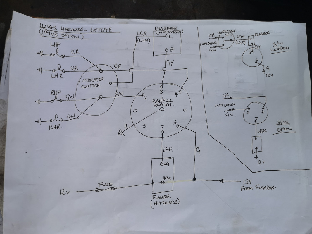
You utilise conventional markings for the indicator flasher and DIN for hazard...
KISS
All the wiring codes are standard BMC and similar to BS23b (not sure if that's the correct BS number) but too much for the average end user and many an auto-electrician.
Re: hazard switch wiring circuit
Posted: Sat May 13, 2023 8:09 am
by Cliff4WD
You're being a bit negative IMO.

It's just a simple hand drawn sketch showing where the loose coloured wires in the loom go, illustrating the outcome of our conversation within the context of this thread and what is present on my own vehicle. I included the hazard loom kit part number in the title which was also discussed in the previous posts, so the sketch is relevant in the context of our discussion, it's not intended as a stand alone schematic.