I am working a few problems at the same time. I do not think they are all related but I will break them down one by one.
Flashers / Turn signals: They do not work. The 4-way hazard lights work. If I jump +12v power to the nodes on the indicator stalk - the appropriate light bulbs illuminate.
I am confused by the presence of the second flasher in the dash. I know that the small 2 prong flasher is part of the hazard light circuit. I think the second flasher relay is part of the trailer light circuit but I am only guessing. My green book does not have a wire diagram that shows the trailer light or the hazard switch - so I do not have much of a reference. Any ideas on how the two flashers work together or where to test next to get my turn signals to work?
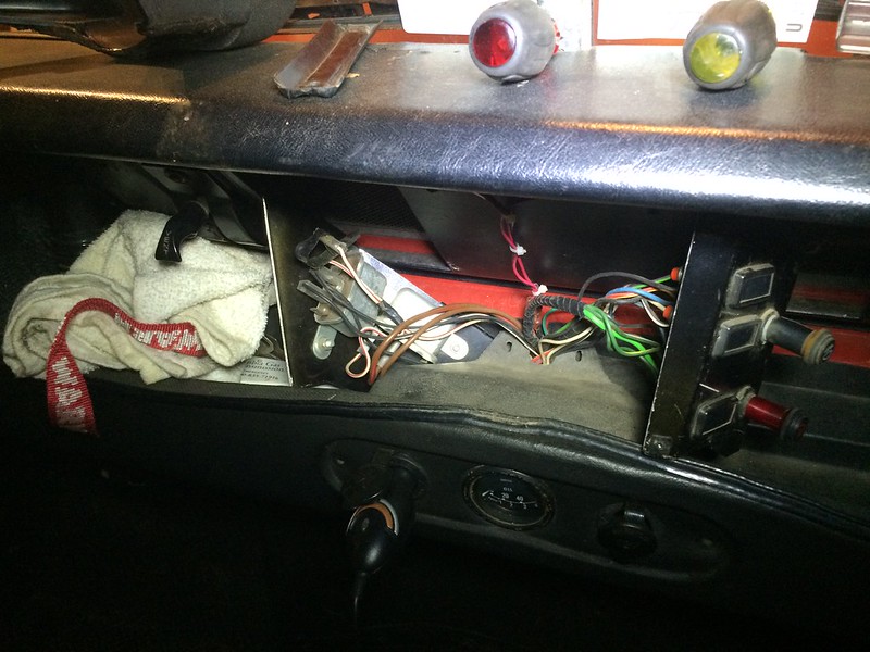
Also - I am not sure if this related - but what do those large relays do that are co-located in the center dash console? (see photo) What circuit are they part of? There is a wire not connected to a prong on one of the relays but it is taped out of the way and appears to have been that way for a very long time. Everything worked until about a week or so ago.
Last edited by firemanshort on Wed Mar 30, 2016 1:14 am, edited 1 time in total.
-----------------------------------
Firemanshort
Virginia, USA
Either your handbook or the manual shows the separate, accessory loom for hazard. The small FL5 flasher behind the gauges is for indicate. The larger FL5 is for hazard. The hazard sub loom is a bridge between the main harness to and from the indicator switch and two or three other loose wires. The other end of this sub loom runs to the hazard switch. The two or three relays behind the centre panel have nothing to do with hazard or flash.
As per your handbook and workshop manual; one relay is for start (item 1 page 138 of the handbook {issue 2, 1/1980}), one is for brake fail if equipped and I forget the third, probably fuel pump. Two are standard, the third is market specific.
The trailer warning light was not working on my second Stage 1 when I bought it, because it was not wired correctly. I'm afraid all I can remember about how I fixed it after it became subject to new MOT requirements is that it wasn't shown in the wiring diagrams in either my Stage 1 owner's or workshop manuals, but that I did find it in the wiring diagram for the V8 90/110 here:-
The second flasher works when a trailer is attached. It earths on the trailer circuit and so if no trailer is attached, it flashes once when you indicate.
The relays are for the indicators, I think. Of course mine has different wiring to yours.
Oh, and for the indicators not working. Clearly the circuit is intact otherwise the hazards would not work. The hazards use a different switch circuit to the indicators but they (the two circuits) are connected at the switch. So I would start with the indicator stalk and use a multimeter to find where the current fails. My guess is that it is the indicator stalk at fault.
Finally, I fitted a lower voltage relay for the head lights and indicators to reduce the sparking that burns the indicator terminals.