Wiring help

Technical questions and answers
Post Reply
5988
Posts: 692
Joined: Fri Mar 13, 2009 8:57 pm
Location: Lincolnshire

Wiring help

Post by 5988 »

Working through this, as best I can with a combination of a S3 manual and RRC manual - as the S3 V8 supliment I have is a copy, and the wiring codes are almost inpossible to read

I have some spare wires,

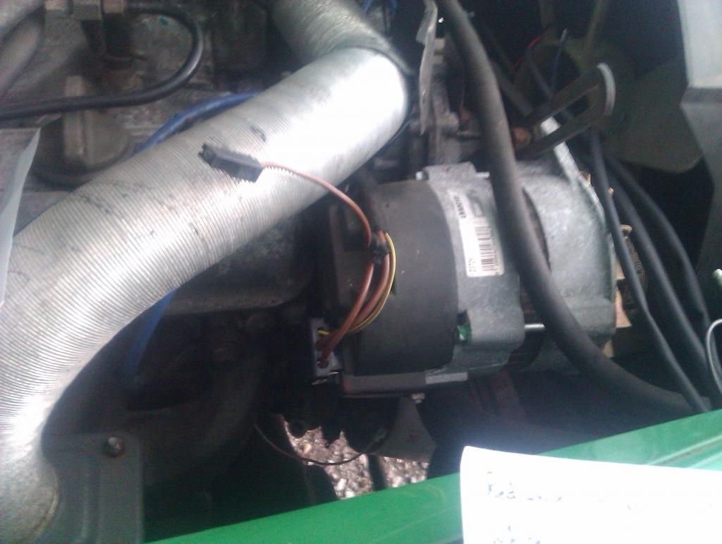
This bworn one at the alternator - none of the LR's I have have a fourth connection, just the three on the lucar block connnector
Image


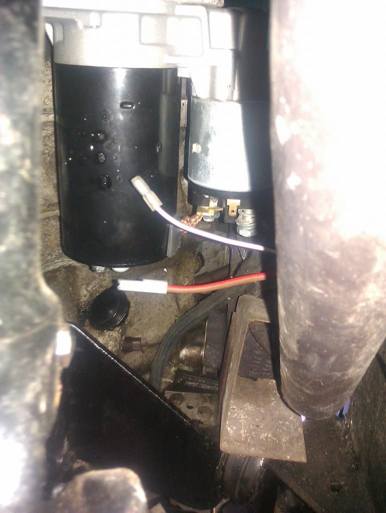
I have two connecotrs at the starter, but only one spade - presumnably one will be the trigger for the starter, but the other?
Image
Also does the routing of the loom, pass the exhaust and through the engine mount look about right?
There doesnt seem to be any wires anywhere near going to the brake shuttle switch either, anyone able to trace theres and let me know where it comes from?

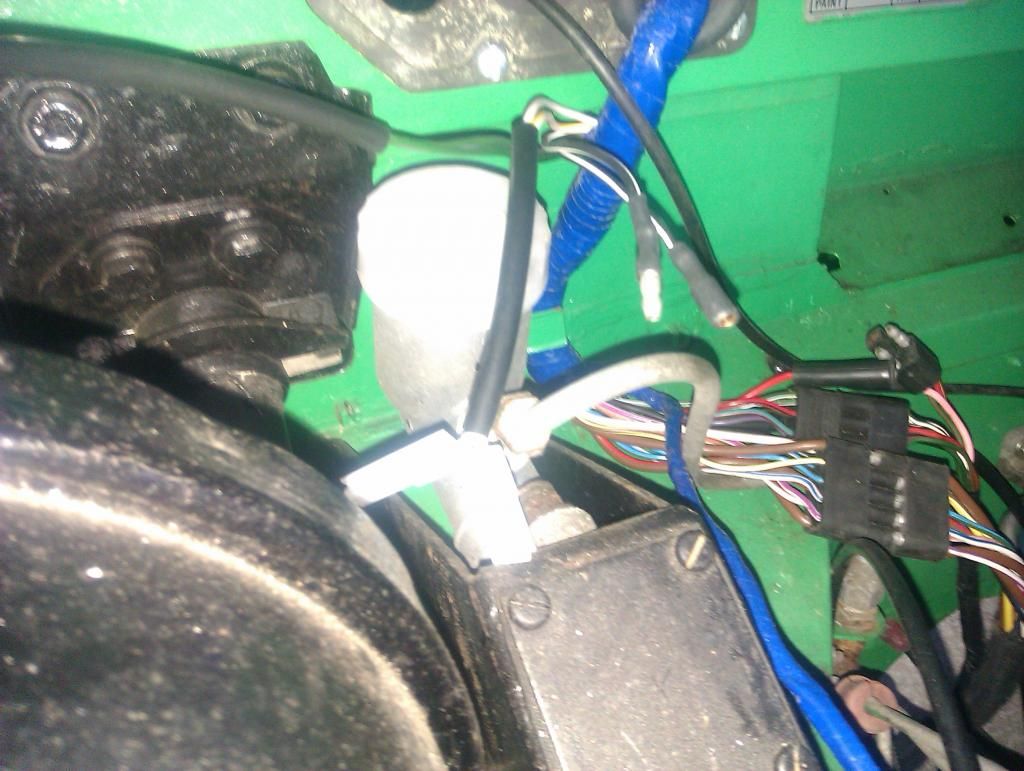
By the clutch pedal I have these two black and white bullet connectors , the other two spares I think are the choke switch
Image

Also I dont have a servo vacuun switch, which the manual seems to suggest I should? - any photos of that area would be really helpful
disco2hse
Posts: 1638
Joined: Sun Apr 27, 2008 3:51 am
Location: Auckland NZ

Re: Wiring help

Post by disco2hse »

5988 wrote:Working through this, as best I can with a combination of a S3 manual and RRC manual - as the S3 V8 supliment I have is a copy, and the wiring codes are almost inpossible to read
Look at the V8 Supplement online here, page 86-6 onward.
5988 wrote:This bworn one at the alternator - none of the LR's I have have a fourth connection, just the three on the lucar block connnector
Brown normally goes to starter solenoid.
5988 wrote:I have two connecotrs at the starter, but only one spade - presumnably one will be the trigger for the starter, but the other?
Is the thick one brown from the alternator?
5988 wrote:Also does the routing of the loom, pass the exhaust and through the engine mount look about right?
Yes, it appears to be on the correct side of the heat shield.
5988 wrote:There doesnt seem to be any wires anywhere near going to the brake shuttle switch either, anyone able to trace theres and let me know where it comes from?

By the clutch pedal I have these two black and white bullet connectors , the other two spares I think are the choke switch

Also I dont have a servo vacuun switch, which the manual seems to suggest I should? - any photos of that area would be really helpful
Black and white are the brake servo vacuum loss switch
Alan

1983 ex-army FFR 109 Stage 1
2005 Disco 2 HSE TD5
5988
Posts: 692
Joined: Fri Mar 13, 2009 8:57 pm
Location: Lincolnshire

Re: Wiring help

Post by 5988 »

Thanks

The manual I've been using is the one from this site, unfortunately the wiring codes are unreadable. Paper reprint is on order so hopefully next weekend all will be clear

Brown wire at the alternator just doesn't see to have anywhere to go on the alternator - it won't reach anywhere else.
A the starter there are two sets of brown wires,I think one set from the alternator, one to the fuse box. They are ring terminals - it's the two spades that aren't adding up, have a 70's RRc to look at so will see what that reveals

Thanks re the vacuum loss switch
User avatar
Geoff
Posts: 599
Joined: Sat Oct 29, 2011 2:21 am
Location: Leicester UK

Re: Wiring help

Post by Geoff »

In that picture of your starter, is the wire at the top purple and white? On my vehicles and in the manual there is a purple and white wire going from the starter to the coil via a ballast resistor - it's something to do with giving some sort of extra 'boost' or something to the distributor when starting - sorry for the untechnical description but I can't remember anything clearer - I'm sure you can google it - I read up on it when I googled the ballast resistor one time when I was fault finding a distributor problem. Hope this helps?

(To clarify (?!), technically I think the wire from the starter bypasses the ballast resistor through which the coil normally draws its current when the engine is running, but its physically attached to the 'current out' end of the resistor so that both sources of current share a common wire from resistor to coil - hope auto electricians aren't rolling their eyes at this description! - the good news I think is that if you don't have a ballast resistor you don't have to worry about any of this!)

PS I don't have a servo vacuum switch on either of mine either - but I do have what, according to the parts book, look like genuine original blanking plugs! (which tends to suggest they were quite commonly not fitted) - they're on the front face of the servo unit, 'neath the brake fluid reservoir. Also the wires to the brake fluid pressure switch are black and white too.
2 1981 Stage One 109 V8 SWs
Image
Post Reply